


FOX 500 DA6 • Installation and Operation
Installation and Operation, cont’d
2-8
FOX 500 DA6 • Installation and Operation
2-9
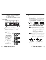
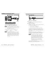
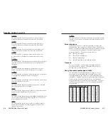
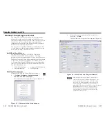
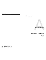
Rear panel serial ports connection
Do not tin the wires!
Controlling
Device
Ground ( )
Receive (Rx)
Transmit (Tx)
Ground ( )
Receive (Rx)
Transmit (Tx)
Bidirectional
RS-232
OVER FIBER
Tx Rx
NA
REMOTE
RS-232
ALARM
Tx Rx
1 2
Function
Pin
TX
RX
Gnd
Transmit data
Receive data
Signal ground
NOTE
For the RS-232 Over Fiber port, cross the Tx and Rx
lines only once between the source and the target.
Figure 2-6 — RS-232 connectors
N
The RS-232 Over Fiber port is for transmission of serial
signals, such as projector control signals, between the DA
and receiver.
The Remote RS-232 port is for remote control of the DA
and receiver.
N
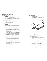
The length of exposed wires is critical. The ideal length is
3/16" (5 mm).
•
If the stripped section of wire is longer than 3/16",
the exposed wires may touch, causing a short circuit
between them.
•
If the stripped section of wire is shorter than 3/16",
wires can be easily pulled out even if tightly fastened
by the captive screws.
N
The rear panel Remote RS-232 port is active only if the
front panel Configuration port is not in use. If a front
panel configuration connection is made, the Remote
RS-232 port becomes inactive and the front panel
Configuration port is active.
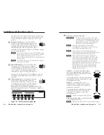
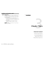
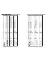
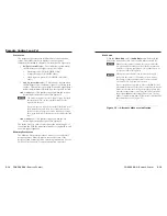
Alarm outputs connection
REMOTE
RS-232
ALARM
Tx Rx
1 2
Pin 1 and pin 2 are
shorted together when
no light is detected.
Do not tin the wires!
Figure 2-7 — Alarms connector
N
The length of exposed wires is critical. The ideal length is
3/16" (5 mm).
•
If the stripped section of wire is longer than 3/16",
the exposed wires may touch, causing a short circuit
between them.
•
If the stripped section of wire is shorter than 3/16",
wires can be easily pulled out even if tightly fastened
by the captive screws.
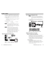
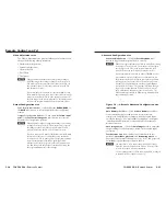
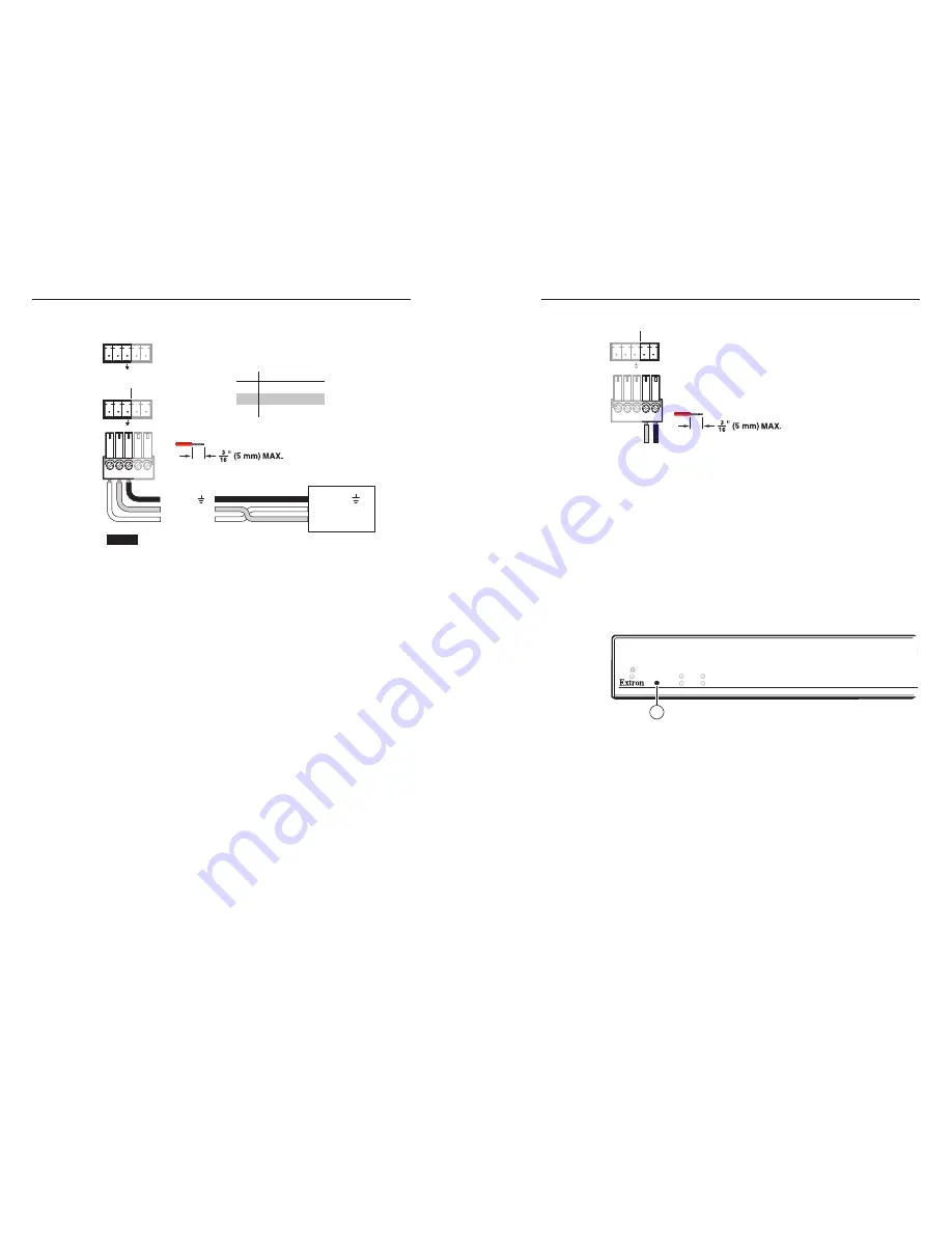
Front panel Configuration port
RGB
AUDIO
LINK 1
CONFIG
LINK 2 (OPTIONAL)
9
Figure 2-8 — FOX 500 DA6 front panel
N
This port is for remote control of the DA or the receiver(s),
not
for the over fiber RS-232 link.
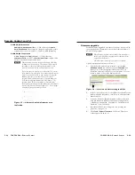
i
Configuration port
— This 2.5 mm mini stereo jack serves
the same serial communications function as the rear panel
Remote RS-232 port, but is easier to access than the rear
port after the unit has been installed and cabled. The
optional 9-pin D to 2.5 mm mini jack TRS RS-232 cable,
part
#70-335-01
(figure 2-9), can be used for this connection.


