11
NOTES:
•
The IPL EXP RIO8 provides a maximum output of 19 watts, combined, for all the DC output ports together.
•
The IPL EXP RIO8 requires a PoE+ source that provides at least 48 watts (see
more detailed information on power input requirements in the
IPL EXP I/O Series User Guide
).
•
See the
Global Configurator Help File
for details on the Limit and Over conditions.
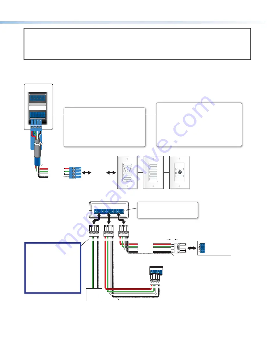
Control — eBUS
+V +S -S G
eBUS (PWR 3W)
1 2 3
G
DIGITAL I/O
4
MUTE
VOLUME
VIDEO
DVD
PC
DOC CAM
LAPTOP
VIDEO
PC
VOLUME
DISPLAY
OFF
ON
Rear Panel,
IPL EXP 200
eBUS Accessory Port
Connect the first eBUS device to this port, then connect other
eBUS devices and accessories to that device in the desired
topology (daisy chain, star, or combination).
• Wire the connectors the same at both ends for every eBUS
device.
• See the
eBUS Technology Reference Guide
for the
recommended distance from the expansion interface or
control processor to the last eBUS device and maximum
quantity of devices per control processor.
• The IPL EXP can provide power to the button panel devices.
eBUS port
on an
eBUS device
(button
panel or
similar
device)
+S
+V
-S
G
+ Signal
+12 VDC
- Signal
Ground
Drain Wires
eBUS Port Monitoring
Use this port to connect button panels for intuitive control of the
system once the panels are configured. The port is always on,
unless the total load reaches the overload condition.
Global Configurator software provides a way to monitor these ports.
•
Normal operation mode
—The load drawn by connected
devices is below the maximum power threshold.
•
Limit mode
—The total load at this port has reached the
maximum threshold power.
•
Overload mode
— The load exceeds maximum threshold
power usage and enters the fault state. The eBUS port shuts off.
Power and eBUS communication will be restored after power
draw from the connected devices falls back below the threshold.
+V
G
-S
+S
+V
G
-S
+S
+V
G
-S
+S
eBUS DISTRIBUTION HUB
-S
+V +S
G
eBUS (PWR 3W)
IPL EXP
Rear Panel
+
V
+
S
G
– S
eBUS port on an
EBP or other
eBUS device
G
-S
+S
+V
Tie drain wires to ground.
X
G
-S
+S
G
-S
+S
Tie drain wires to ground.
G
-S
+S
+V
+
Signal
-
Signal
+
12 VDC
Ground
G
-S
+S
+V
G
-S
+S
+V
Powered
eBUS
device(s)
eBUS Connections
• Connect up to four (4) eBUS devices to the
eBUS distribution hub (EBDB MINI).
• Wire the connectors the same at both ends.
ATTENTION:
• Do NOT connect the power pin
to any device that is already
powered by the IPL EXP or an
IPCP control processor or by
an additional power supply.
• NE connectez PAS la broche
d'alimentation à un appareil
déjà alimenté par le IPL EXP
ou le processeur de contrôle
IPCP ou par une autre source
d'alimentation.
3/16" (5 mm) Max.
EBDB MINI
Rear Panel
(or use
an EBDB
10-port hub)


