IR Link • Installation and Operation
IR Link • Installation and Operation
Installation and Operation, cont’d
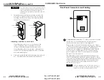
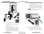
External
power supply
(12VDC, 1 A max.)
IR Link
B
A
Stand-alone IR Link with power supply and IR Emitter
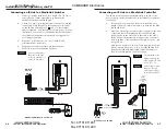
+12VDC
Ground ( )
B
A
D
Modulated IR
(IR Link)
Ground ( )
D
B
B
IR
Emitter
White striped
wire only
IR Link
To an
IR controlled
Extron
device
MLA
Remote
SIGNAL
IR LINK
2-11
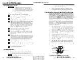
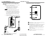
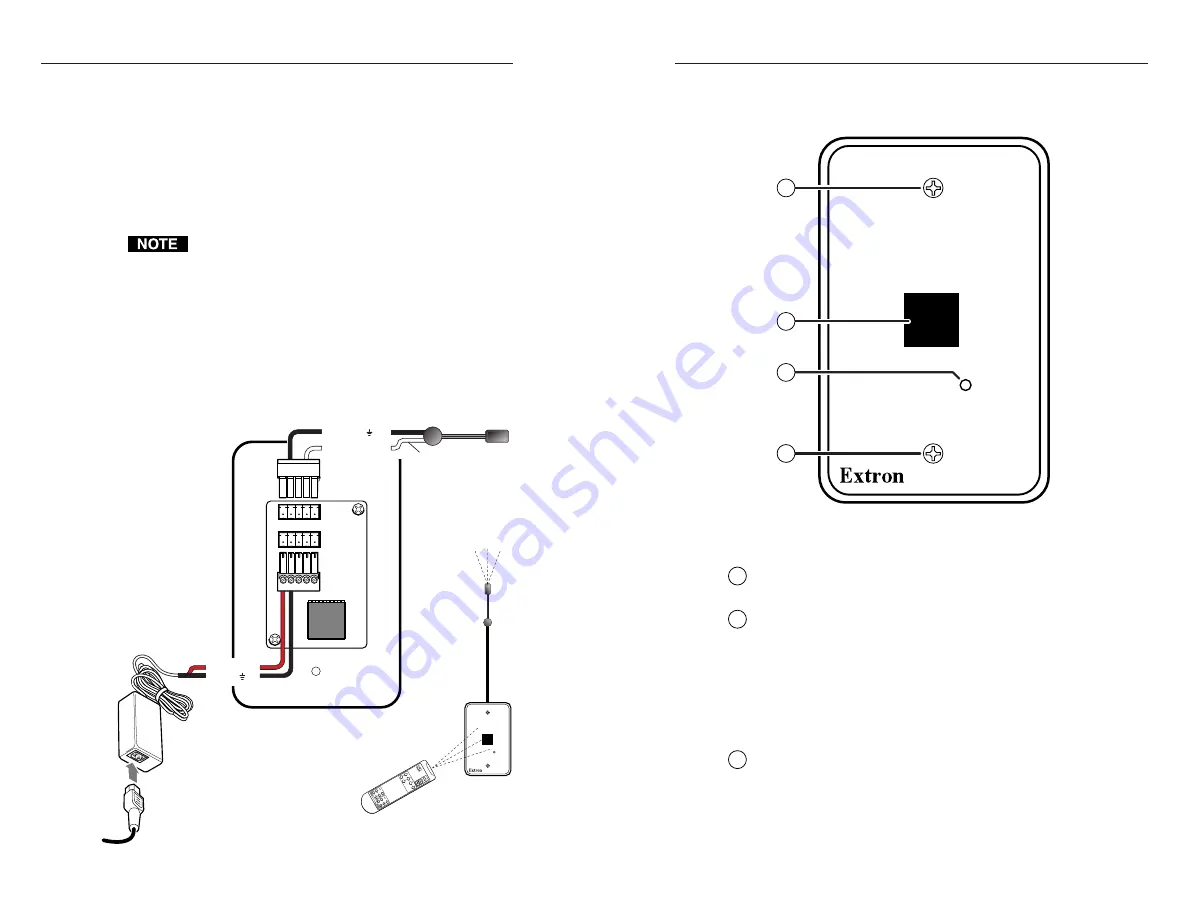
1
Mounting screws
— These two screws attach the IR Link to the
electrical wall box, mud ring, or furniture.
2
IR signal pickup device
— The IR Link receives infrared signals
from an IR remote control through this window so it can be
converted to an electronic signal that is sent to a connected
Extron device to control that device. The output carrier
frequency is 38 kHz, and the IR Link should be used only with
Extron products.
When you use the IR remote control, point it directly at this
window for best results.
3
Signal LED
— This LED lights to indicate that the IR Link is
receiving an infrared signal.
SIGNAL
IR LINK
1
2
3
1
Front Panel Features and Operation
2-10
Connecting an IR Link to a power supply and an
IR Emitter
An external, stand-alone power supply is only necessary if the
IR Link is not part of a MediaLink system.
1.
Attach an external 12VDC power supply to pins A
(+12VDC) and B (ground) of a 3.5 mm captive screw
connector, and plug it into one of the IR Link’s
communications connectors as shown below.
Connect a maximum of one IR Link. Do not connect
more than one IR Link (either in parallel or in series).
2.
Attach the black wire of an Extron IR Emitter to pin B
(ground) and the white striped wire to pin D (IR signal) of
a 3.5 mm captive screw connector, and plug it into the IR
Link’s remaining communications connector, as shown
below. Two or three emitters can be wired to the same
connector, if needed.
3.
Place the head of the IR Emitter near or in front of the IR
pickup device of the IR-controllable Extron product.
im Vertrieb von
CAMBOARD Electronics
www.camboard.de
Tel. 07131 911201
Fax 07131 911203
ce-info@camboard.de