
IR Link • Specifications, Part Numbers
IR Link • Specifications, Part Numbers
Specifications, Part Numbers, Dimensions
A-3
A-2
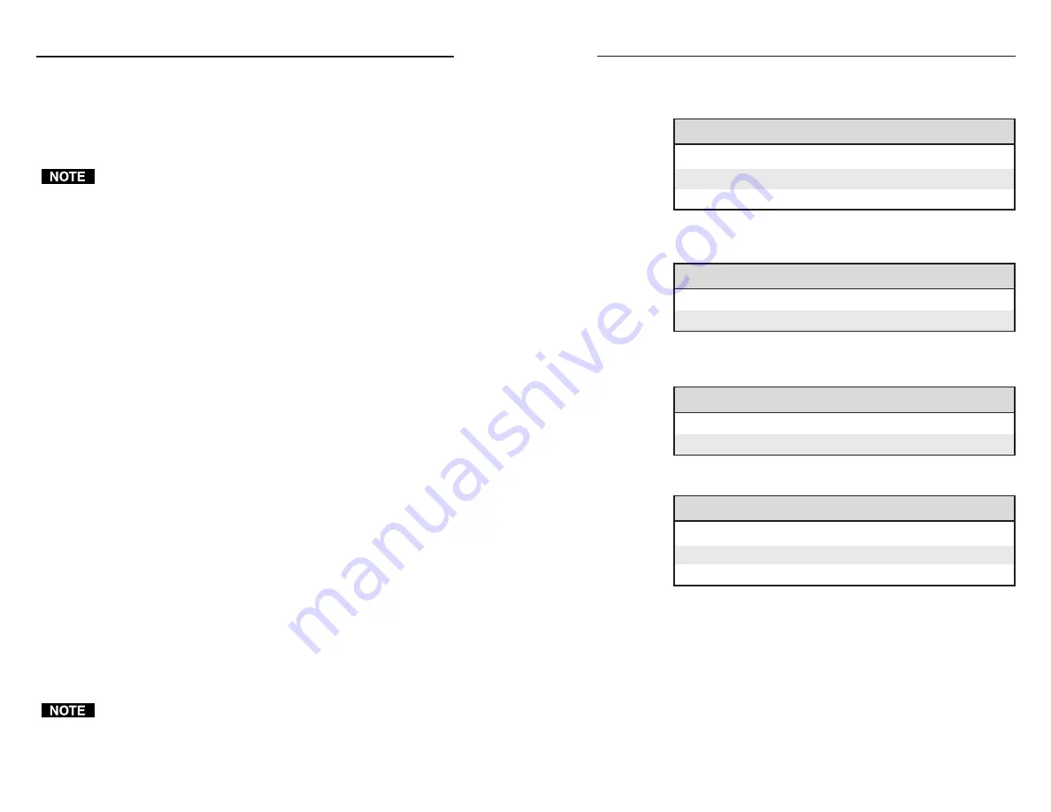
Included Parts
These items are included in each order for an IR Link:
Included parts
Part number
IR Link (grey, black, white)
60-404-01, -02, -03
3.5 mm, 5-pole captive screw connectors
10-319-10
IR Link User’s Manual
68-602-01
Accessories
Miscellaneous accessories
Part number
12VDC, 1 A power supply
70-055-01
IR Emitter
19-823-01
Cables
Comm-link cable
Part number
50 feet/15.2 meters long
26-461-01
100 feet/30.5 meters long
26-461-02
Specifications
Control/remote — IR repeater
IR controller module ................... Extron IR remote controls only
IR output carrier frequency ........ 38 kHz
Use the IR Link with Extron products only.
General
Power ............................................. 12VDC, 0.21 A from an Extron MediaLink
Controller (MLC), MediaLink Switcher
(MLS), or external power supply
Temperature/humidity .............. Storage -40° to +158°F (-40° to +70°C) /
10% to 90%, non-condensing
Ope32° to +122°F (0° to +50°C) /
10% to 90%, non-condensing
Rack mount ................................... No, but furniture/wall mountable
Enclosure type .............................. Metal
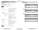
Enclosure dimensions
Faceplate (1-gang) .... 4.5" H x 2.8" W x 0.1” D (11.4 cm H x
7.1 cm W x 0.3 cm D) (1-gang)
Circuit board ............ 2.6" H x 1.75" W x 0.8" D
(4.1 cm H x 4.4 cm W x 2.0 cm D)
(Depth includes connectors and
components.)
Allow at least 1.5” (3.8 cm) depth within
the wall box or furniture to accommodate
the circuit board, connectors, and cables.
Product weight ............................. 0.1 lbs (<0.1 kg)
Shipping weight ........................... 1 lb (0.5 kg)
Vibration ....................................... ISTA/NSTA 1A in carton
(International Safe Transit Association)
Listings .......................................... UL, CUL as a component of the
MediaLink Controller (MLC 206)
Compliances ................................. CE, FCC Class A, VCCI, AS/NZS, ICES as
a component of the MediaLink
Controller (MLC 206)
MTBF ............................................. 30,000 hours
Warranty ....................................... 3 years parts and labor
Specifications are subject to change without notice.
Conductor gauges in Extron Comm-Link cables
red and black single strands (for power/ground)
18 AWG
white and violet shielded single strands (for signals)
22 AWG
drain wire
24 AWG
im Vertrieb von
CAMBOARD Electronics
www.camboard.de
Tel. 07131 911201
Fax 07131 911203
ce-info@camboard.de


