IR Link • Specifications, Part Numbers
IR Link • Specifications, Part Numbers
Specifications, Part Numbers, Dimensions, cont’d
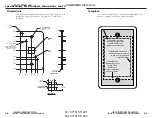
Dimensions
The following diagram has been reduced to fit on the page. All
dimensions are given in inches. The symbol “ø“ indicates a
diameter.
A-4
0.040 RECESS
ON NEAR SIDE.
.775
+.050
-.000
SQ.
.640 SQ.
.388
DETAIL 'A'
.320
R.062
(4 PLCS)
0.000
0.000
0.610
3.890
4.500
1.395
2.790
DETAIL
'A'
Ø.156 THRU WITH
Ø.290x82˚ C'SINK
(2 PLCS)
2.250
3.375
0.720
2.070
1.125
1.808
1.450
Ø.133
THRU
R.060
TOP EDGE
ALL AROUND
R.250
(4 PLCS)
(.100)
PEM INSERT BSOS-440-16
OR EQUIV. INSERT FROM
NEAR SIDE. (2 REQ'D)
Ø.166
+.003/
-.000
THRU
(2 PLCS)
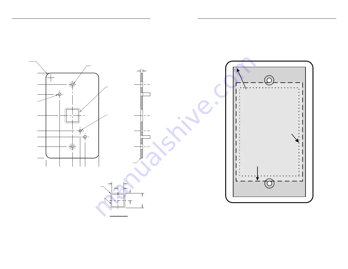
The medium grey area
indicates the cut-out area
(4.13"H x 2.3"W) for a
regular electrical wall box.
The dashed line
indicates the cut-out
area (3.13"H x
2.13"W) for a
compact, adjustable
electrical wall box.
To install the IR Link
without a
wall box, use the cut-out area
(2.8" H x 1.9" W) indicated
by the dotted line.
Template
Use a 100% size photocopy of the cut-out template below as a
guide for cutting a hole in the wall or furniture.
A-5
im Vertrieb von
CAMBOARD Electronics
www.camboard.de
Tel. 07131 911201
Fax 07131 911203
ce-info@camboard.de


