background image

i

IR Link• Table of Contents

Table of Contents

Chapter 1 • Introduction

.......................................................... 1-1

About the IR Link

................................................................... 1-2

Features

...................................................................................... 1-2

Chapter 2 • Installation and Operation

......................... 2-1

Installation Overview

.......................................................... 2-2

UL Requirements

.................................................................... 2-2

Preparing the Site and Installing the Wall Box

..... 2-3

Rear Panel Connectors and Cabling

............................. 2-5

Connecting an IR Link to a MediaLink Switcher .................. 2-6
Connecting an IR Link to a MediaLink Controller ............... 2-7
Connecting an IR Link to a power supply and
an IR Emitter ........................................................................ 2-10

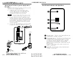
Front Panel Features and Operation

......................... 2-11

Testing/Troubleshooting

.................................................. 2-12

Appendix A • Specifications

Part Numbers,

and Dimensions

............................................................................. A-1

Specifications

......................................................................... A-2

Included Parts

......................................................................... A-3

Accessories

............................................................................... A-3

Cables

......................................................................................... A-3

Dimensions

.............................................................................. A-4

Template

.................................................................................... A-5

68-602-01  

Rev. B

Printed in the USA

02 02

All trademarks mentioned in this manual are the properties of their respective owners.

im Vertrieb von

            CAMBOARD Electronics

www.camboard.de

Tel. 07131 911201
Fax 07131 911203

ce-info@camboard.de

Summary of Contents for IR Link

Page 1: ...5 Joo Seng Road 04 01 PM Industrial Building Singapore 368363 65 6383 4400 Fax 65 6383 4664 Extron Electronics Japan Daisan DMJ Building 6F 3 9 1 Kudan Minami Chiyoda ku Tokyo 102 0074 Japan 81 3 3511 7655 Fax 81 3 3511 7656 www extron com 2002 Extron Electronics All rights reserved Infrared Signal Repeater 68 602 01 Printed in the USA IR Link im Vertrieb von CAMBOARD Electronics www camboard de T...

Page 2: ...nur von qualifiziertem Servicepersonal durchgeführt werden Die internen Komponenten des Gerätes sind wartungsfrei Zur Vermeidung eines elektrischen Schocks versuchen Sie in keinem Fall dieses Gerät selbst öffnen da beim Entfernen der Abdeckungen die Gefahr eines elektrischen Schlags und oder andere Gefahren bestehen Schlitze und Öffnungen Wenn das Gerät Schlitze oder Löcher im Gehäuse aufweist die...

Page 3: ... Link to a MediaLink Controller 2 7 Connecting an IR Link to a power supply and an IR Emitter 2 10 Front Panel Features and Operation 2 11 Testing Troubleshooting 2 12 Appendix A Specifications Part Numbers and Dimensions A 1 Specifications A 2 Included Parts A 3 Accessories A 3 Cables A 3 Dimensions A 4 Template A 5 68 602 01 Rev B Printed in the USA 02 02 All trademarks mentioned in this manual ...

Page 4: ... Table of Contents Table of Contents cont d IR Link 1 Chapter One Introduction About the IR Link Features im Vertrieb von CAMBOARD Electronics www camboard de Tel 07131 911201 Fax 07131 911203 ce info camboard de ...

Page 5: ...equency IR signals Infrared signals received by the IR Link are passed on to the Extron device which can be installed out of the direct line of sight of the IR remote controls Features Grey black or white faceplates The IR Link is offered in three shades for integration into a variety of environments Furniture and wall mountability The IR Link can be mounted onto or in furniture or walls either di...

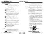
Page 6: ...units must be installed in accordance with the National Electrical Code and with local electrical codes and used with UL approved electrical boxes See UL Require ments on this page To install and set up an IR Link follow these steps 1 Turn the equipment off Make sure that the IR Link is disconnected from the power source 2 Select the site and run cables through the wall or furniture to where the I...

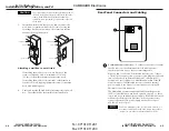
Page 7: ... of one 1 IR Link to a device Do not connect more than one IR Link either in parallel or in series to a switcher or a MediaLink Controller CAUTION To prevent short circuits the outer foil shield can be cut back to the point where the cable exits the cable clamp Both braided and foil shields should be connected to an equipment ground at the other end of the cable 7 Insert the wall box into the open...

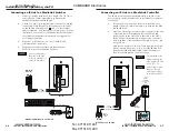
Page 8: ...ed Wire the cable as shown in the following illustration Connectors are included with the IR Link but the cable must be purchased separately See appendix A for cable part numbers 3 Plug the 5 pole connector into one of the IR Link s communications connectors 4 Plug the other end of the cable into the rear panel MLC IR port of the MediaLink Switcher Connecting an IR Link to a MediaLink Controller T...

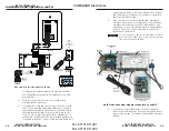
Page 9: ...additional MediaLink control module that will be connected in a daisy chain Wire both ends of the cable identically pin A to pin A pin B to pin B etc Up to a total of 4 control modules in any combination of models and one IR Link can be daisy chained together and connected to the MLC as long as each control module has a 2 9 unique address Refer to the Control Modules User s Manual and the Relay Co...

Page 10: ... lights to indicate that the IR Link is receiving an infrared signal SIGNAL IR LINK 1 2 3 1 Front Panel Features and Operation 2 10 Connecting an IR Link to a power supply and an IR Emitter An external stand alone power supply is only necessary if the IR Link is not part of a MediaLink system 1 Attach an external 12VDC power supply to pins A 12VDC and B ground of a 3 5 mm captive screw connector a...

Page 11: ...k s Signal LED and observe the Extron device or the display connected to the device 2A If the Signal LED does not light when the IR remote control s button is pressed check the captive screw connector wiring at the MediaLink Controller or MediaLink Switcher if applicable and at the IR Link s connectors If the conductor assignments are not correct at both ends of the cable the IR Link will not turn...

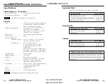
Page 12: ...ng 32 to 122 F 0 to 50 C 10 to 90 non condensing Rack mount No but furniture wall mountable Enclosure type Metal Enclosure dimensions Faceplate 1 gang 4 5 H x 2 8 W x 0 1 D 11 4 cm H x 7 1 cm W x 0 3 cm D 1 gang Circuit board 2 6 H x 1 75 W x 0 8 D 4 1 cm H x 4 4 cm W x 2 0 cm D Depth includes connectors and components Allow at least 1 5 3 8 cm depth within the wall box or furniture to accommodate...

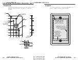
Page 13: ...33 THRU R 060 TOP EDGE ALL AROUND R 250 4 PLCS 100 PEM INSERT BSOS 440 16 OR EQUIV INSERT FROM NEAR SIDE 2 REQ D Ø 166 003 000 THRU 2 PLCS The medium grey area indicates the cut out area 4 13 H x 2 3 W for a regular electrical wall box The dashed line indicates the cut out area 3 13 H x 2 13 W for a compact adjustable electrical wall box To install the IR Link without a wall box use the cut out ar...

Page 14: ...ions Part Numbers Specifications Part Numbers Dimensions cont d This page was intentionally left blank A 6 A 7 This page was intentionally left blank im Vertrieb von CAMBOARD Electronics www camboard de Tel 07131 911201 Fax 07131 911203 ce info camboard de ...

Page 15: ...cations Part Numbers Specifications Part Numbers Dimensions cont d A 8 This page was intentionally left blank im Vertrieb von CAMBOARD Electronics www camboard de Tel 07131 911201 Fax 07131 911203 ce info camboard de ...

Reviews: