
IR Link • Installation and Operation
IR Link • Installation and Operation
Installation and Operation, cont’d
2-5
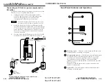
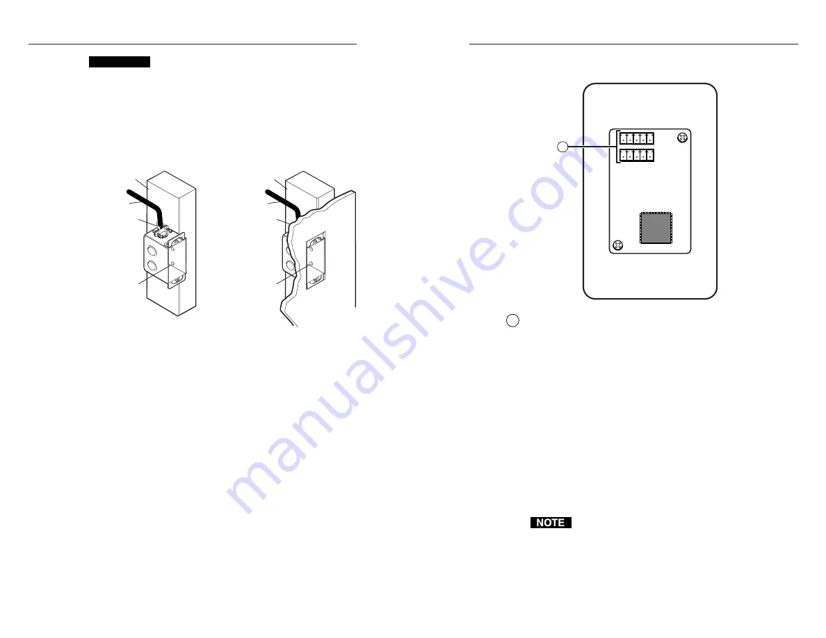
Rear Panel Connectors and Cabling
2-4
1
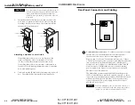
Communications connectors
— Use these connectors to connect
the IR Link to another Extron device(s). Both connectors
function the same way, so they are interchangeable.
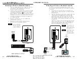
Plug one end of an Extron Comm-Link cable into one of these
3.5 mm, 5-pole captive screw connectors, and plug the other end
into a connector on an Extron MediaLink Controller (MLC),
MediaLink Control Module, or MediaLink Switcher. If the IR
Link is not part of a MediaLink system, connect an external
power supply to one connector, and connect one or more IR
Emitters to the other connector.
The MediaLink Switcher and MediaLink Controller provide
12VDC to the IR Link on pin B and a ground on pin A, so there
is no need for an additional power supply. If the IR Link is used
with another Extron device (switcher, scan converter, scaler),
connect an external DC power supply (such as Extron part
#70-055-01) to those pins.
Connect a maximum of one (1) IR Link to a device. Do
not connect more than one IR Link (either in parallel or
in series) to a switcher or a MediaLink Controller.
CAUTION
To prevent short circuits, the outer foil shield can be
cut back to the point where the cable exits the cable
clamp. Both braided and foil shields should be
connected to an equipment ground at the other end
of the cable.
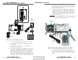
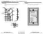
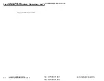
7.
Insert the wall box into the opening, and attach it to the
wall, stud, or furniture with nails or screws, leaving the
front edge flush with the outer wall or furniture surface.
See the following illustration.
Installation Cable
Cable Clamp
Wall Stud
Installation Cable
Cable Clamp
Wall Stud
Screws or Nails
Screws or Nails
Attaching a wall box to a wall stud
If attaching the wall box to wood, use four #8 or #10
screws or 10-penny nails. A minimum of 1/2 inch
(1.3 cm) of screw threads must penetrate the wood.
If attaching the wall box to metal studs or furniture, use
four #8 or #10 self-tapping sheet metal screws or machine
bolts with matching nuts.
8.
Cable and test the IR Link before fastening it into the wall
box. The cables will be inaccessible after installation.
1
im Vertrieb von
CAMBOARD Electronics
www.camboard.de
Tel. 07131 911201
Fax 07131 911203
ce-info@camboard.de


