
IR Link • Installation and Operation
IR Link • Installation and Operation
Installation and Operation, cont’d
MLC
IR / RCM
port
A B C D
IR / RCM
IR Link
Modulated IR
+12VDC
Ground ( )
D
B
D
B
A
A
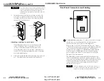
MLC 206 to an IR Link
MLC 206
Extron
MediaLink Controller
MLC 206
DISPLAY
POWER
VOLUME
MAX/
MIN
VCR
DVD
Laptop
IR Link
MLA
Remote
SIGNAL
IR LINK
Total
distance
from MLC:
150' (45.7 m)
max.
IR Link
Modulated IR
+12VDC
Ground ( )
C
D
B
A
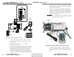
MediaLink Switcher to an IR Link
A B C
MediaLink
Switcher
MLC/IR
MLS 506MA Rear Panel
100-240V 0.2A 50/60 Hz
.5A MAX
INPUT 1
VIDEO
Y
C
R-Y
B-Y
YUV
Y
R-Y
B-Y
VIDEO
S-VIDEO
Y
C
INPUT 2
VIDEO
Y
C
R-Y
B-Y
INPUT 3
VIDEO
Y
C
R-Y
B-Y
INPUT 4
R
H/
HV
G
V
B
INPUT 5
R
H/
HV
G
V
B
INPUT 6
R
H/
HV
G
V
B
RGB
R
H/
HV
G
V
B
4 ohm
MONO AMPLIFIED OUTPUT
COMM
8 ohm
70V
L
R
L
R
L
R
L
R
AUX/MIX
EFFECTS
L
R
SEND
L
R
RETURN
MLC/IR
RS232
CONTACT CLOSURE
A B C
AUDIO OUT
FIXED
VARIABLE
L
R
L
R
L
L
R
R
L
R
IR Link
MLA-Remote
150' (45.7 m) max.
SIGNAL
IR LINK
2-6
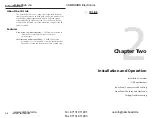
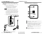
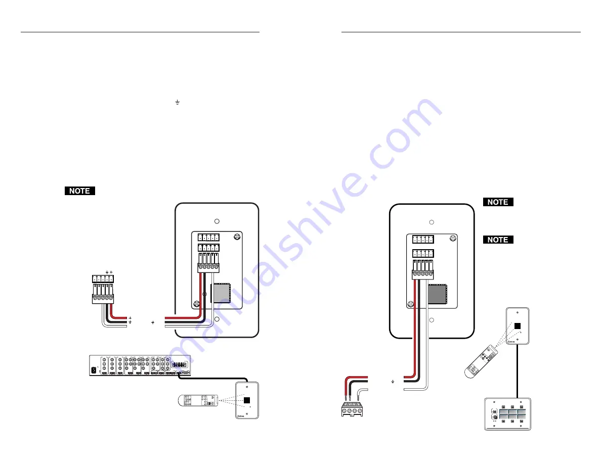
Connecting an IR Link to a MediaLink Switcher
1.
If it hasn’t already been done, cut a length (150’/45.7 m or
less) of Extron Comm-Link cable to go between the
MediaLink Switcher and the IR Link.
2.
Attach a 3.5 mm, 5-pole captive screw connector to each end
of the cable. Only three wires (between pins A, B, and D
on the IR Link end and pins C, , and + on the switcher
end) are required. Wire the cable as shown in the following
illustration. Connectors are included with the IR Link, but
the cable must be purchased separately. See appendix A
for cable part numbers.
3.
Plug the 5-pole connector into one of the IR Link’s
communications connectors.
4.
Plug the other end of the cable into the rear panel
MLC/IR port of the MediaLink Switcher.
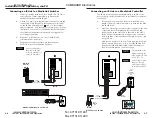
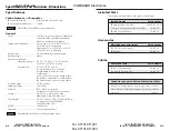
Connecting an IR Link to a MediaLink Controller
The IR Link can either be connected directly to an MLC or be
part of a daisy chain of MediaLink Control Modules connected
to the MLC.
1.
If it wasn’t done when the wall box was installed, cut a
length of Extron Comm-Link cable to go between the MLC
and the IR Link.
2.
Attach a 3.5 mm, 5-pole captive screw connector to the end
of the cable that will be plugged into the IR Link, and
connect wires on the other end of the cable to the MLC’s
IR/RCM 4-pole direct insertion captive screw connector.
Wire both ends of the cable identically (pin A to pin A, pin
B to pin B, etc.).
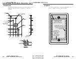
Only three wires (pins A, B, and D) are required (as shown
below), but use four wires (A, B, C, D) if the IR Link will
be daisy chained with MediaLink Control Modules (as
shown in the illustration on the next page).
2-7
The maximum total
distance between the
MLC and the IR Link
is 150’ (45.7 m).
Do not connect more
than one IR Link
(either in parallel or
in series) to an MLC.
Do not connect more
than one (1) IR Link
(either in parallel or in
series) to a switcher.
im Vertrieb von
CAMBOARD Electronics
www.camboard.de
Tel. 07131 911201
Fax 07131 911203
ce-info@camboard.de


