

NOTE:
•
Balanced or unbalanced stereo sources can be connected with the 6-pole connectors.
•
When using the 5-pole CSR 6 captive-screw to RCA adapter, connect it so the far left plug is inserted into the far left jack of
the 6-pole input.
ATTENTION:
•
For unbalanced audio outputs, connect the sleeves to the ground contact. DO NOT connect the sleeves to the negative
(-) contacts.
•
Pour l’audio asymétrique, connectez les manchons au contact au sol. Ne PAS connecter les manchons aux contacts
négatifs (–).
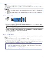
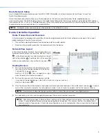
Step 3 — Remote Ports
STANDBY
G
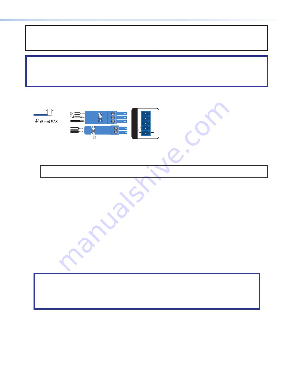
REMOTE
Do not tin
the wires!
Tx
Rx
G
G
STANDBY
Tx
Rx
G
RS-232
Figure 5.
Remote Volume Control and Standby Ports
•
Standby mode is forced when the
Standby
pin is connected to the second G pin. The power LED on the front panel
lights amber when the amplifier is in Standby mode, indicating that the amplifier is still receiving power despite the fact
that it has turned off all the outputs.
NOTE:
The enabling and disabling of the auto-standby timer is handled through SIS or DSP Configurator. For more
details, consult the
NetPA U 2002 SB User Guide
.
•
Connect a 3.5 mm, 3-pole captive screw connector to remotely control the volume via SIS commands, and connect a 3.5
mm, 2-pole captive screw to place the amplifier into Standby mode.
Protocol for the RS-232 port:
•
38,400 baud
•
1 stop bit
•
8 data bits
•
no parity
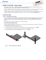
Step 4 — Speaker Wiring
Connect a 4-pin, 5 mm captive-screw connector for two channels of speaker output on the NetPA U 2002 SB amplifier. Each
port has a screw flange to secure the plug to the connector (see
figure 6
on the next page to learn how to wire the captive screw
connector).
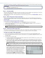
Follow the instructions below to configure the rear panel for the NetPA U 2002 SB:
•
For stereo modes, connect a 4-pin, 5 mm captive screw connector for two channels of speaker outputs. The port has a
screw flange to secure the plug to the connector.
•
For mono modes, connect the same 4-pin, 5 mm captive screw connector but wire only the middle speaker output pins for a
single channel of speaker output (see
figure 6
to learn how to wire the speaker output).
ATTENTION:
•
Do not connect the speaker output connector to the amplifier until the output mode has been set properly (see
“Setting the Output Mode”
on the next page for details).
•
Ne connectez pas le connecteur de sortie du haut-parleur à l’amplificateur tant que le mode de sortie n’a
pas êtê rêglê correctment (voir
“Setting the Output Mode”
(Dêfinir le mode sortie) ci-dessous pour plus
d’informations).
3


