Setup Guide — P/2 DA2xi MT
Extron
USA - West
Headquarters
+800.633.9876
Inside USA / Canada Only
+1.714.491.1500
+1.714.491.1517
FAX
Extron
USA - East
+800.633.9876
Inside USA / Canada Only
+1.919.863.1794
+1.919.863.1797
FAX
Extron
Europe
+800.3987.6673
Inside Europe Only
+31.33.453.4040
+31.33.453.4050
FAX
Extron
Asia
+800.7339.8766
Inside Asia Only
+65.6383.4400
+65.6383.4664
FAX
Extron
Japan
+81.3.3511.7655
+81.3.3511.7656
FAX
Extron
China
+400.883.1568
Inside China Only
+86.21.3760.1568
+86.21.3760.1566
FAX
Extron
Middle East
+971.4.2991800
+971.4.2991880
FAX
© 2010 Extron Electronics. All rights reserved.
www.extron.com
68-713-50
Rev. A
01 10
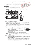
Do not tin the wires!
Unbalanced Stereo Output
Balanced Stereo Output
Ring
Sleeve(s)
Tip
Tip
Ring
Sleeve(s)
Tip
Tip
NO GROUND HERE.
NO GROUND HERE.
L
R
L
R
C
Connect the sleeve to ground (Gnd). Connecting the sleeve to a negative (-) terminal
will damage the audio output circuits.
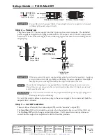
Step 4 — Power up
Plug the external 12 V power supply into this 2-pole captive screw connector. The included
power supply is shipped with a plug installed on the DC output cord. If the DC output cord
needs to be cut to a different length, see the following figure and notes for reinstalling the DC
output plug.
Power Supply
Output Cord
Captive Screw
Connector
3
5
SECTION A–A
Ridges
Smooth
A
A
Tie Wrap
C
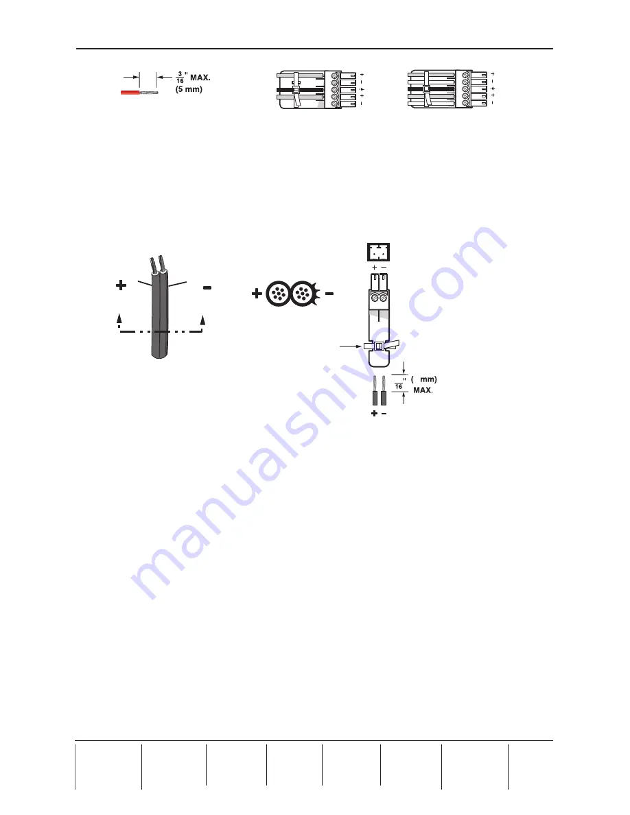
When you connect the power supply, voltage polarity is extremely important. Applying
power with incorrect voltage polarity could damage the power supply and the amplifier.
Identify the power cord negative lead by the ridges on the side of the cord.
N
Do not tin the stripped power supply leads before installing the captive screw connector.
Tinned wires are not as secure in the connectors and could pull out. Strip the power cord
jacket 5 mm from the end.
W
The two power cord wires must be kept separate while the power supply is plugged in.
Remove power before continuing.
To verify the polarity before connection, plug in the power supply with no load and check the
output with a voltmeter.
Step 5 — Set DIP switches
These switches affect only the video output (
g
), not the “monitor” output (
d
).
The
Gain/Peak
DIP switch should be on (up) when the output cable is over 100 feet (30.5 m).
The
Out Imp DIP
switch changes output impedance. If all connections and operations are
correct, but the output has no picture, switch to the other position.


