background image

© 2007  Extron Electronics.  All rights reserved.

Extron Electronics, USA

1230 South Lewis Street

Anaheim, CA  92805

800.633.9876  714.491.1500  

FAX  714.491.1517

Extron Electronics, Europe

Beeldschermweg 6C

3821 AH Amersfoort, The Netherlands

+800.3987.6673  +31.33.453.4040

FAX +31.33.453.4050

Extron Electronics, Asia

135 Joo Seng Rd. #04-01

PM Industrial Bldg., Singapore  368363

+800.7339.8766  +65.6383.4400  

FAX  +65.6383.4664

Extron Electronics, Japan

Kyodo Building, 16 Ichibancho

Chiyoda-ku, Tokyo 102-0082

Japan

+81.3.3511.7655  FAX  +81.3.3511.7656

www.extron.com

User’s Guide

12 VDC, 3 Amp Power Supply

68-1253-01  

Rev. C

07 07

PS 123

Summary of Contents for PS 123

Page 1: ...Amersfoort The Netherlands 800 3987 6673 31 33 453 4040 FAX 31 33 453 4050 Extron Electronics Asia 135 Joo Seng Rd 04 01 PM Industrial Bldg Singapore 368363 800 7339 8766 65 6383 4400 FAX 65 6383 4664...

Page 2: ...den Stromunterbrechung Um das Ger t auf sichere Weise vom Netz zu trennen sollten Sie alle Netzkabel aus der R ckseite des Ger tes aus der externen Stomversorgung falls dies m glich ist oder aus der W...

Page 3: ...s equipment generates uses and can radiate radio frequency energy and if not installed and used in accordance with the instruction manual may cause harmful interference to radio communications Operati...

Page 4: ...it Adapter Kit 3 UL requirements 4 Installing the flexible conduit cable 4 Output power wiring the DC output connectors 7 Mounting options 8 Rack mounting 8 UL rack mounting requirements 8 Rack mounti...

Page 5: ...peration green and overload operation red The rack mountable PS 123 has a 1U high quarter rack wide 8 5 deep metal enclosure allowing the PS 123 to take advantage of a variety of mounting options Fron...

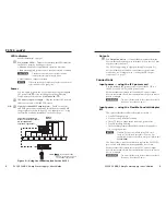
Page 6: ...he PS 123 meets the UL 2043 requirements Figure 2 Using the conduit option for the PS 123 Outputs d DC Output connectors Connect the power cables from the devices that will receive power from the PS 1...

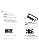
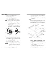
Page 7: ...e conduit cable assembly to the PS 123 as follows 1 Unplug the IEC power cord 2 Remove and retain the two Phillips head screws that secure the EMT plate figure 3 below to the PS 123 rear panel OUTPUTS...

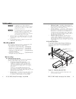
Page 8: ...step 10 figure 6 above to ensure that it firmly secures the conduit EMT adapter plate to the power supply 15 Use the six screws you removed in step 3 to secure the top cover of the PS 123 back onto i...

Page 9: ...t temperature of the rack environment may be greater than room ambient temperature Therefore consider installing the equipment in an environment compatible with the maximum ambient temperature Tma spe...

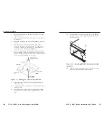
Page 10: ...5 Align the mounting screws with the slots in the brackets and place the power supply against the surface with the screws through the bracket slots 6 Slide the unit slightly forward or back then tigh...

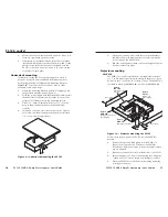
Page 11: ...lose to the ceiling as desired 8 Secure the L shaped bracket to the U bolt using the included hex nuts washers and lock washers Tighten the hex nuts securely C Be sure to tighten the hex nuts securely...

Page 12: ...d secure it by fully tightening the set screws FRONT REAR Cable Input from Ceiling AV control Cable Access Hole Bottom Plate Filler Plate Cable Output to Projector COM 1 LAN UID 093 012 052 POW ER 12V...

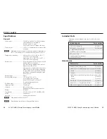
Page 13: ...n all outputs 42 watts Power output 12 VDC 3 A maximum total current of the 8 outputs N Maximum output current is rated at an ambient temperature of 40 C It decreases to 2 A at an ambient temperature...

Page 14: ...PS 123 12 VDC 3 Amp Power Supply User s Guide PS 123 cont d 18 PS 123 12 VDC 3 Amp Power Supply User s Guide 19 This page was intentionally left blank This page was intentionally left blank...

Page 15: ...PS 123 12 VDC 3 Amp Power Supply User s Guide PS 123 cont d 20 This page was intentionally left blank...

Reviews: