3
For threaded rod installation
NOTES:
•
1/4 inch or
3/8
inch diameter threaded rods are recommended for
installing this product.
•
The threaded rod should be properly secured to the ceiling structure.
For example, properly fasten a unistrut to the ceiling structure and
attach threaded rods using nuts and washers.
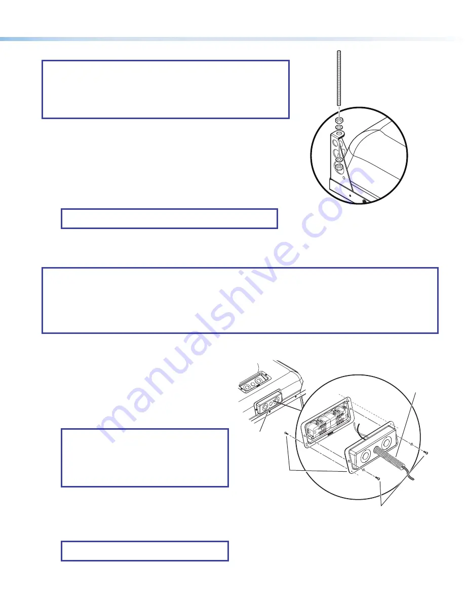
Secure the frame to the structural ceiling using threaded rods.
To do this:
a.
Attach four rods to the support structure by using, for example
a unistrut, one over each corner of the PVM 220 installation location.
b.
Attach a rod to each corner securing point of the PVM 220 with nuts and
washers (see figure 5 at right).
c.
Adjust all the nuts to secure the PVM 220 to the ceiling, keeping it level and
without lifting the unit from the T-grid.
NOTE:
The nuts and washers for threaded rod installation are not
supplied with the PVM 220.
Step 4 — Run AC power wiring to the AC module in the PVM 220.
If power is not available close to the installation location, install a junction box or power source at the area.
NOTES:
•
This must be done by a qualified electrician and must meet local and national electrical, building and safety codes and
all the regulatory requirements (see
•
Use metal conduit only to run wire to the AC module.
•
Do not run power cable in the same conduit as signal cables.
•
Use 12 AWG gauge solid copper wire only, as required by the installed power receptacles.
Run the power cable through metal conduit and wire it into the
PVM 220 power module.
To do this:
a.
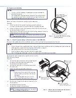
Unscrew the two center screws (left and right side) of
the power inlet/control panel and remove from
the enclosure (see figure 6 at right).
b.
Unscrew the two screws on the corners and detach
the outer cover.
c.
Attach the metal conduit to the outer cover.
NOTES:
•
Remove only the knockouts that are to be
used for cabling. Leave intact the unused
knockouts.
•
The three knockout sizes are ½ inch to
¾ inch, ¾ to 1 inch, and 1 to 1¼ inch.
d.
Run the wires through the conduit and connect to the
AC receptacles.
e.
Reassemble the power module.
f.
Reattach the module to the enclosure.
NOTE:
The power module outlets must be used to
power installed AV devices only.
Figure 5.
Secure the PVM 220 to the ceiling
with threaded rod.
1/2" Conduit
Knockout
Remove screws and
remove power module
from the PVM 220 enclosure.
Attach a metal
conduit to the
outer cover.
Remove screws and
detach the outer cover
from power module.
å
ä
ã
Insert threaded rods
through holes on the ends
of the mounting plate.
Attach washers and nuts and secure.
Figure 6.
Remove the power module from the enclosure
to attach the metal conduit.


