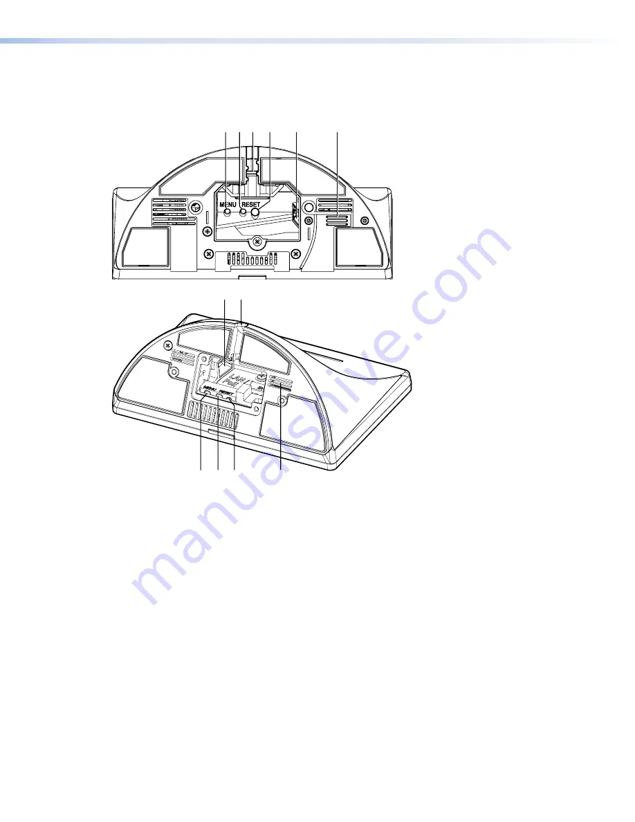
TLP Pro 525T, TLP Pro 725T, and TLP Pro 1025T Base
Figure 5 shows the TLP Pro 725T (top) and the TLP Pro 525T base (bottom). TLP Pro 1025T
base is similar to the TLP Pro 725T base.
A
AB
BC
C D
D E
E
F
F
E
E C
C
A
A B
B D
D
F
F
Figure 5.
TLP Pro 725T (top) and TLP Pro 525T (bottom) Base
A
Menu button
B
Reset button
— Pressing the
Reset
button allows the unit to be reset in any of three
different modes and can also be used to toggle between enabling and disabling the DHCP
client (see
C
Cable guide
— The Ethernet cable is inserted through this hole at the back of the base (see
“LAN/PoE connector” below).
D
Reset LED
— Provides feedback about the reset status when the user presses the
Reset
button (see
).
E
LAN/PoE connector
— Attach the LAN/PoE cable to this RJ-45 port.
An Extron IPL Pro control processor must also be connected to the same network domain
as the TouchLink Pro touchpanel (see the
for a list of suggested models).
The network port has two LEDs. The green LED lights steadily to indicate that the
touchpanel is connected correctly to a network. The yellow LED blinks to indicate that data
is being passed to or from the touchpanel.
figure 5
Menu button
Reset button
Cable guide
Reset LED
LAN/PoE connector
A
B
C
D
E
F
TLP Pro 525, 725, and 1025 Series Touchpanels • Panel Features
12


