TP Receivers • Installation and Operation
TP Receivers • Installation and Operation
Installation and Operation, cont’d
5
.
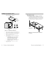
For through-surface mounting (all except TP R 15HD A)
,
insert four #8 wood screws through the bracket and into
the four pilot holes. Tighten all four screws to secure the
receiver in place.
6
.
For under-surface mounting
, insert #8 wood screws into
the four pilot holes. Tighten each screw into the mounting
surface until just less than 1/4” of the screw protrudes.
7
.
For under-surface mounting
, align the mounting screws
with the slots in the brackets and place the receiver against
the surface, with the screws through the bracket slots.
8
.
For under-surface mounting
, slide the receiver slightly
forward or back, then tighten all four screws to secure the
switcher in place.
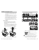
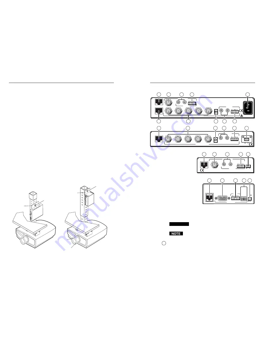
Projector mounting
All of the receiver models can be mounted on a projector
bracket using the appropriate optional mounting bracket,
Extron’s Mini Projector Mounting Kit (part #70-217-01)
(
TP R 15 HD A
) or Projector Mounting Kit (part #70-077-04)
(
all other models
).
Secure the mounting bracket to the receiver using two machine
screws in the side of the receiver (
TP R 15HD A
) or the three #8
machine screws provided (
all other models
). Secure the
receiver to a projector mount or other surface by inserting the
mounting bolt through the bracket’s slotted hole (figure 2-6).
A
A
-V
O
U
TP
UT
O
U
TP
U
T
P
O
W
E
R
1
5
V
.5
A
D
C
L
R
B
A
V
IN
P
U
T
V
ID
E
O
TP R AV
TP R 15HD A
Mounting
Bolt
C S
YN
C
SO
G
C V
IDE
O
N/C
L
R
A
U
D
IO
O
U
T
P
U
T
A
V
IN
P
U
T
R
G
B
P
O
W
E
R
1
5
V
.3
4
A
M
A
X
Mounting
Bolt
Projector
Mounting
Bracket
Projector
Mounting
Bracket
Figure 2-6 — Projector bracket mounting a receiver
2-10
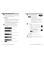
Rear panel features and cabling
TP R BNC A
TP R BNC AV
TP R AV
RGB INPUT
A-V INPUT
50/60 Hz
100-240V 0.3A
RGB OUTPUT
R
VIDEO
G
B
H/HV
V
A
AUDIO
AUDIO
L
R
B
SOG
C SYNC
L
R
A
A-V AUDIO
L
R
B
L
R
RGB INPUT
RGB OUTPUT
R
G
B
H/HV
V
A
AUDIO
L
R
B
SOG
C SYNC
POWER
15V .5A DC
L
R
TP R 15HD A
A
A-V OUTPUT
L
R
B
A-V INPUT
VIDEO
AUDIO
POWER
15V .5A DC
L
R
C SYNC
SOG
C VIDEO
N/C
L
R
AUDIO
OUTPUT
AV INPUT
RGB
POWER
15V
.34A MAX
9
5
5
8
2
6
7
8
9
8
1
7
5
3
2
6
7
8
9
1
4
8
9
1
3
7
Figure 2-7 — Installation features, TP receivers
Transmitted signal cabling
CAUTION
Do not connect this device to a computer data or
telecommunications network
RJ-45 termination must comply with the TIA/EIA
T 568A
wiring standards for all connections.
1
RGB video transmission connector —
Attach one end of a TP
cable to this RJ-45 female connector (figure 2-7). Attach the
other end to an Extron TP 15HD or BNC transmitter. See
Termination of TP cable
on page 2-15 for pin assignments.
2-11


