
IMPOR
TANT
:
Go to www
.extron.com for the
complete user guide and installation
instructions befor
e connecting the
product to the power sour
ce.
IMPOR
TANT
:
Go to www
.extron.com for the
complete user guide and installation
instructions befor
e connecting the
product to the power sour
ce.
MTP DA4 and DA8 • Setup Guide
This guide provides basic instructions for
J9
Disable
Mute
(Default)
or
Enable
Mute
J3
Serial
or
Audio
(Default)
an experienced installer to set up and operate
the Extron MTP DA distribution amplifier.
Pre-installation — Jumpers
See figure
1
at the right or see “Termination
and Mute Jumpering” in the MTP DA4 and
DA8 User Guide for more information.
NOTE:
The jumpers have no effect when
the DA is part of an MTP CV/SV series, or
VTT001/VTR001 system.
Jumper J3
This sets the DA to properly terminate RGB video as well as the audio (default) or serial
portion of the input signal.
Jumper J9
This sets the DA to always pass the audio or serial link regardless of the contact closure
mute status (default). It can also be set to mute the audio or serial link when its video mute
function is activated.
Use 2 mounting holes on
opposite corners.
1/2 Rack Width False Front
Face Plate
(2) 4-40 x 3/16" screws
6" Deep Rack Shelf
MTP D
A SERIE
S
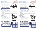
Installation
Step 1 — Mounting
Turn off or disconnect all equipment power sources
and mount the MTP DA as required. A mounting
example is at the right (see figure
2
). See “Mounting”
in the user guide for more mounting options.
Step 2 — Input from the Transmitter
Terminate a TP cable as shown in figure
3
. Connect
the cable into a MTP transmitter and into the AV
1
2
3
4
A/V INPUT
A/V OUTPUTS
Insert
TP Wires
Pins:
1234567 8
input connector.
Step 3 — Outputs to the Receivers
Terminate up to four or eight (depending on
model) TP cables as shown in figure
3
. Connect
the cables into the DA AV output ports and into
receivers that are compatible with the transmitter.
NOTES:
•
The inputs and outputs should be
terminated using the same standard on both
ends of the cable.
•
Only use the TIA/EIA T568A standard
when using Enhanced Skew-Free™ AV cable.
Pin
T568 A
Wire Color
T568 B
Wire Color
1
White-green
White-orange
2
Green
Orange
3
White-orange
White-green
4
Blue
Blue
5
White-blue
White-blue
6
Orange
Green
7
White-brown
White-brown
8
Brown
Brown
Figure 1.
Jumpers
Figure 2.
6-inch Deep Rack
Shelf Mount
Figure 3.
TP Cable Termination
MTP DA4 and DA8 • Setup Guide
This guide provides basic instructions for
J9
Disable
Mute
(Default)
or
Enable
Mute
J3
Serial
or
Audio
(Default)
an experienced installer to set up and operate
the Extron MTP DA distribution amplifier.
Pre-installation — Jumpers
See figure
1
at the right or see “Termination
and Mute Jumpering” in the MTP DA4 and
MTP DA8 User Guide for more information.
NOTE:
The jumpers have no effect when
the DA is part of an MTP CV/SV series, or
VTT001/VTR001 system.
Jumper J3
This sets the DA to properly terminate RGB video as well as the audio (default) or serial
portion of the input signal.
Jumper J9
This sets the DA to always pass the audio or serial link regardless of the contact closure
mute status (default). It can also be set to mute the audio or serial link when its video mute
function is activated.
Use 2 mounting holes on
opposite corners.
1/2 Rack Width False Front
Face Plate
(2) 4-40 x 3/16" screws
6" Deep Rack Shelf
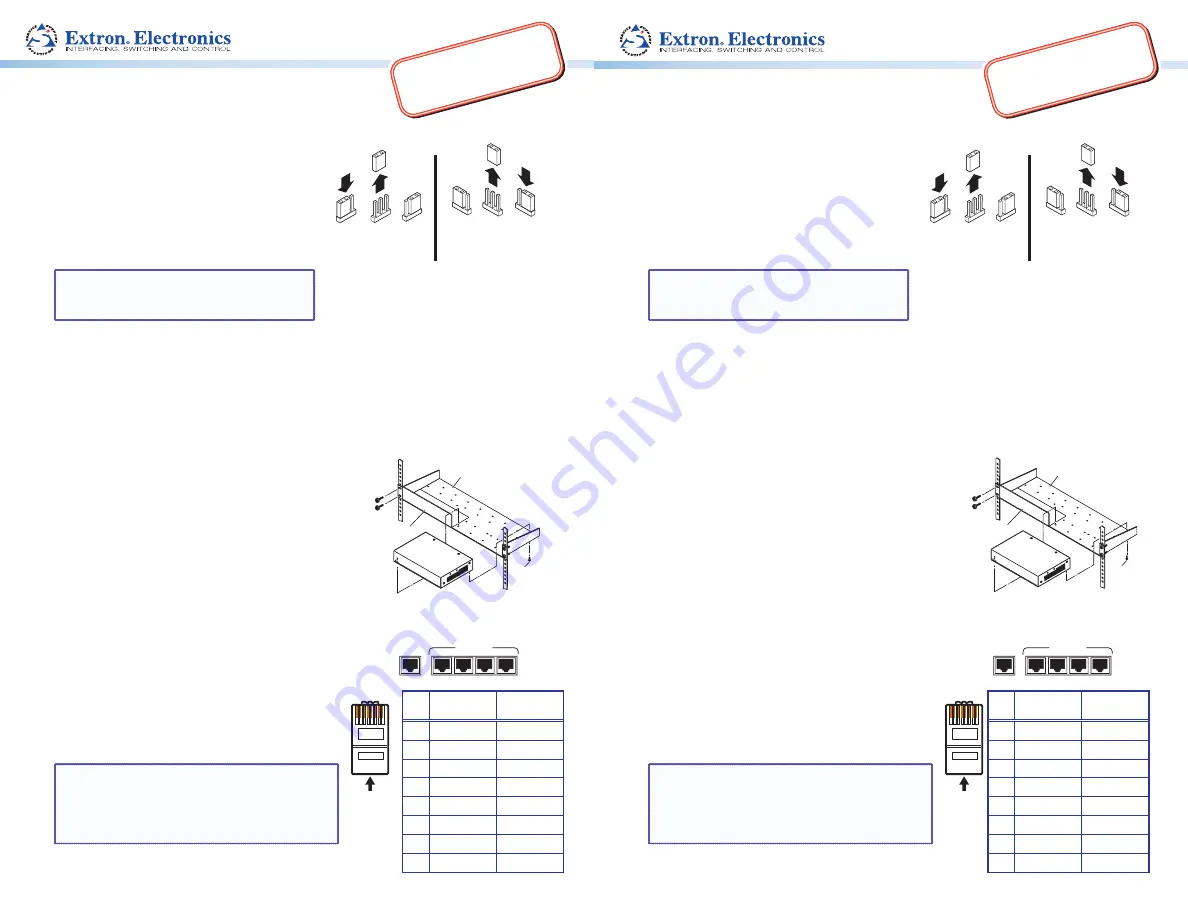
MTP D
A SERIES
Installation
Step 1 — Mounting
Turn off or disconnect all equipment power sources
and mount the MTP DA as required. A mounting
example is at the right (see figure
2
). See “Mounting”
in the user guide for more mounting options.
Step 2 — Input from the Transmitter
Terminate a TP cable as shown in figure
3
. Connect
the cable into an MTP transmitter and into the AV
1
2
3
4
A/V INPUT
A/V OUTPUTS
Insert
TP Wires
Pins:
1234567 8
input connector on the DA.
Step 3 — Outputs to the Receivers
Terminate up to four or eight (depending on
model) TP cables as shown in figure
3
. Connect
the cables into the DA AV output ports and into
receivers that are compatible with the transmitter.
NOTES:
•
The inputs and outputs should be
terminated using the same standard on both
ends of the cable.
•
Only use the TIA/EIA T568A standard
when using Enhanced Skew-Free™ AV cable.
Figure 1.
Jumpers
Figure 2.
6-inch Deep Rack
Shelf Mount
Pin
T568 A
Wire Color
T568 B
Wire Color
1
White-green
White-orange
2
Green
Orange
3
White-orange
White-green
4
Blue
Blue
5
White-blue
White-blue
6
Orange
Green
7
White-brown
White-brown
8
Brown
Brown
Figure 3.
TP Cable Termination


