background image

• 

Select 

Scale

 to enable the source image to be scaled to the required resolution and 

frame rate as defined by 

Monitor

 or the 

Fixed

 output format that is selected.

NOTE:

  Scaling is disabled when the output format is set to 

Auto

.

• 

The 

Genlock

 control allows the display output of multiple decoders to be coordinated 

and creates a genlock group. One VND 250 device is selected as the timing reference 
for the output of all the other VND 250 devices in the same decoder genlock group. The 
genlock output from the chosen reference device is connected to the other decoders in 
a daisy chain architecture.
A network-based protocol enables the chosen VND 250 to coordinate the frame timing 
so that all decoders display the same frame simultaneously.

• 

One decoder is selected as the reference (master) unit, and provides the genlock 
signal that is used to synchronize all the other units (slaves).

• 

The 

Genlock

 setting on the master device must be disabled.

• 

The 

Genlock

 setting on the slave devices must be enabled.

• 

The name of the master device must be selected from the 

Framelock


Ref


drop-down list on 

all

 devices in the genlock group (see Framelock ref below).

Framelock Ref

 (

figure 41

4

, on the previous page) controls membership of the decoder 

genlock group. Each member of the group is selected to have the same genlock master, 
including the master itself. When such a group is formed, a network-based protocol permits 
the master to coordinate frame timing so that all decoders are showing frames captured 
at exactly the same times. This requires the separate enabling of the genlock feature, as 
described above.

• 

The 

Clean Switch

 feature allows glitch free transitions when switching between 

decoded streams that may have different resolutions and frame rates. Select the check 
box to activate this option.

NOTE:

  When using 

Clean


Switch

 mode, the scale option must be checked and 

the required output mode must be selected in the 

Output


Format

 drop-down 

list. 

Clean


Switch

 is not supported when switching to an image from a recorded 

stream.

• 

The VND 250 fully supports HDCP. Source images that are HDCP encrypted can only 
be displayed on an HDCP compliant display. Selecting the 

HDCP


Mode

 option forces 

HDCP encryption for all stream types. An HDCP compliant display must be used when 
this option is enabled. If not, a full green screen is displayed for all video streams. 

NOTE:

  Setting this mode improves the 

Clean


Switch

 performance in systems 

where it is necessary to switch between encrypted and non-encrypted stream 
types.

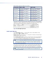
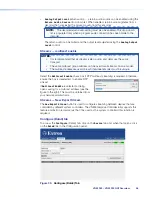
Active


Format

 (

figure 41

3

) shows the current output mode being used on the display.

• 

When the 

Output


Format

 is set to 

auto

, this field reports the source format for the 

current stream.

• 

When the 

Output


Format

 is set to 

monitor

, this field reports the source format that 

has been selected from the EDID of the currently connected display.

• 

When the 

Output


Format

 is set to 

fixed

, this field reports the same mode.


VNM 250 • VNM 250 GUI Overview

60

Summary of Contents for VN-Matrix 250 Series

Page 1: ...68 2236 01 Rev E 01 19 VNE 250 Encoder and VND 250 Decoder VN Matrix 250 Series User Guide Streaming AV Products...

Page 2: ...itio Web de Extron www extron com Instructions de s curit Fran ais AVERTISSEMENT Ce pictogramme D lorsqu il est utilis sur le produit signale l utilisateur la pr sence l int rieur du bo tier du produi...

Page 3: ...EGRATOR TeamWork TouchLink V Lock VideoLounge VN Matrix VoiceLift WallVault WindoWall XTP XTP Systems and ZipClip Registered Service Mark SM S3 Service Support Solutions Trademarks AAP AFL Accu Rate F...

Page 4: ...s interference must be corrected at the expense of the user NOTE For more information on safety guidelines regulatory compliances EMI EMF compatibility accessibility and related topics see the Extron...

Page 5: ...computer or device responses mentioned in this guide the character 0 is used for the number zero and O represents the capital letter o Computer responses and directory paths that do not have variables...

Page 6: ......

Page 7: ...50 Device as the System Controller 28 Configuring the System Controller with a Static IP Address 28 Configuring Other VNM 250 Devices with a Static IP Address 28 Configuring a VNM 250 Series Unit for...

Page 8: ...vel Menu 102 Decode Config Submenu 103 OSD Submenu 104 Network Submenu 104 Output Submenu 107 Video Wall Submenu 108 Test Pattern Submenu 109 Genlock Submenu 110 Reset Submenu 110 Alarms 112 Alarm Typ...

Page 9: ...resented to an end user while being delivered by a VN Matrix encoding device About the VNM 250 The VNE 250 distributes video audio and data input across an IP network to one or more VND 250 decoders T...

Page 10: ...R RETURN AUDIO L R STREAMING CONTROL USB INPUT 1 INPUT 2 COMS I O OUTPUT LAN 1 LAN 2 PC RESET HDMI LOOP THRU LOOP THRU LOOP THRU RGB ACT LINK A MAX POWER 12V AUDIO L Tx Rx PASS THRU ALARM TTL CONTROL...

Page 11: ...controller device Supports all VN Matrix devices including recorders Supports VNM 250 encoders and decoders and PCs running the VNS 104 software decoder Does not support recorders NOTES A small system...

Page 12: ...L MENU NEXT ADJUST STREAM STATUS CONFIG ALARM VND 250 VN MATRIX RGB HDMI OVER IP CONTROL MENU NEXT ADJUST STREAM STATUS CONFIG ALARM Figure 2 Multicast RTP Streaming The source encoder uses RTP to sen...

Page 13: ...ALARM Figure 3 Unicast RTP Streaming RTP provides very low latency which is important for video streaming Unlike other protocols RTP packets include a time stamp If packets are received in the wrong o...

Page 14: ...method of data transfer is unidirectional and can only be sent from an encoder to a decoder High Level Interface HLI is the command protocol that is used to communicate between the VNM Enterprise Con...

Page 15: ...aspect ratio of the decoder output can be controlled by selecting a FILL mode which provides a full screen output or a FOLLOW mode which preserves the original aspect ratio of the original source sign...

Page 16: ...oder USB port allows connection to a local PC while the decoder USB ports allow connection of a mouse and keyboard to remotely control a PC connected to the encoder On screen display aids in identifyi...

Page 17: ...Configuration on page 25 5 Connect the Control connector of the rear panel Coms port three poles of the 5 pole captive screw connector to a control computer Use DataViewer to configure the IP addresse...

Page 18: ...the encoder site 9 If required connect USB cables to allow KVM Function This allows users at the decoder site to take control of the keyboard and mouse of the source computer at the encoder site see...

Page 19: ...SB mini type B port to a control PC for low level configuration using SIS commands B Unit status LEDs provide status information about the unit see Status Information on the next page C LCD display A...

Page 20: ...g streamed for example the unit is currently disabled or in standby mode N A Alarm Red Fully lit indicates that a critical alarm has occurred Flashing indicates an over temperature condition For compl...

Page 21: ...Rx NO G IN G OUT R RETURN AUDIO L R STREAMING CONTROL COMS INPUT I O OUTPUT OUTPUT 1 2 USB A B C D F U S R O J I Q Figure 7 VND 250 Rear Panel A Power B Control Network RJ 45 connector C Streaming Ne...

Page 22: ...z toujours une source d alimentation fournie ou recommand e par Extron L utilisation d une source d alimentation non autoris e annule toute conformit r glementaire et peut endommager la source d alime...

Page 23: ...de fa on permanente une structure de b timent ou une structure similaire If a power strip is used for example within rack mounted installations ensure that the current rating for the power strip and...

Page 24: ...O L R STREAMING CONTROL COMS INPUT I O OUTPUT OUTPUT 1 2 USB LAN 1 LAN 2 PC RESET HDMI LOOP THRU LOOP THRU LOOP THRU RGB ACT LINK A MAX POWER 12V AUDIO L Tx Rx PASS THRU ALARM TTL CONTROL G Tx Rx NO G...

Page 25: ...mode cable to the encoder see figure 6 D or decoder see figure 7 D To use a VNM 250 device as a controller 1 Configure the network settings of the device that is to be used as the system controller s...

Page 26: ...ee the VNM Enterprise Controller User Guide at www extron com If a VNM 250 device is the system controller use the GUI for that device to configure KVM Functionality see VNM 250 GUI Overview on page 3...

Page 27: ...Matrix recorder Data passes through the system unchanged transparently No VNM 250 devices are affected by the commands The serial ports on different devices do not need to share a common baud rate Ho...

Page 28: ...lock Genlock I O VND 250 is used to synchronize the video output on multiple decoders NOTE The VND 250 uses TTL level signalling which is not compatible with normal genlock sources One decoder is sele...

Page 29: ...r VNE 250 two screws to the sides of the port Follow the instructions on the card provided with the brackets This card is also available at www extron com NOTE A full screen green image is displayed w...

Page 30: ...er to be played by the encoder Connect the audio output from this 5 pole captive screw connector to an amplifier or powered speakers see figure 6 P Analog program audio output VND 250 connect the audi...

Page 31: ...250 device the controller cannot detect or control that device Controlling Your System with a VN Matrix Enterprise Controller 1 Connect a PC and a VN Matrix Enterprise Controller to the same network a...

Page 32: ...Matrix Enterprise Controller Device List 4 To configure the system with the Enterprise Controller see the VN Matrix Enterprise Controller User Guide which is available at www extron com VNM 250 System...

Page 33: ...ons 1 Use an RS 232 cable to connect a control PC to the rear panel Coms port of the VNM 250 device see page 19 2 On the PC or laptop open a terminal emulation program such as Extron DataViewer with t...

Page 34: ...efault setting is 1 auto_10_100_1000 NOTE A Gigabit network is recommended for streaming media applications 1a or 11b these options determine whether the IP address of the unit is static or set by DHC...

Page 35: ...may be changed if required All units in the system must have the same port number assigned 19 this option sets the number of the port that communicates with the web server The default value is 80 but...

Page 36: ...dress To configure the system controller with a static IP address 1 Open the configuration menu of each device see page 25 and ensure that the Streaming Network port IP Prov mode option 11 is set to s...

Page 37: ...HCP Server 1 Connect a control PC to the chosen unit and log in as described in steps 1 3 on page 25 Control Network port Streaming Network port 0 Speed Duplex auto_10_100_1000 1 IP Prov mode static 2...

Page 38: ...config with the password of config 2 Select option 11 from the menu and enter the value dhcp 3 Press Enter Options 12 13 and 14 disappear from the menu These values are assigned when the unit contacts...

Page 39: ...ing a Dedicated DHCP Server If required a dedicated DHCP server can be used to provide the IP address settings for the VNM250 device in a system The device that is acting as the system controller must...

Page 40: ...e Options Description 046 WINS NBT Node Type 045 NetBIOS over TCP IP NBDD 044 WINS NBNS Servers 0x1 B nod NetBIOS ov NBNS Addre 043 Vendor Specific Info Embedded w Figure 18 Scope Options Window 1 Ope...

Page 41: ...using the streaming network Replies from the system controller to the local device follow the reverse path From a web browser enter http system controller IP address to access the system controller we...

Page 42: ...e of the following web browsers with the version shown or later Windows Internet Explorer version 8 Mozilla Firefox version 20 Google Chrome version 30 The PC must be on the same network as the VNM 25...

Page 43: ...Shared by Both the Encoder and Decoder Device List see page 36 Accounts see page 37 Alarms see page 38 Alarms Logs see page 39 Upgrade see page 41 Peripherals see page 42 License see page 45 Encoder...

Page 44: ...e All saves all changes on the system On the Device page Save All saves only the changes to that device Help provides a context sensitive help page that explains the features of the tab that is curren...

Page 45: ...count 2 allows read only access The admin and public user names cannot be modified By default the password for the admin account is admin The password for the public account is public The admin accoun...

Page 46: ...m 1 to 12 The date is a number from 1 to 31 Hours is a 24 hours clock number from 0 to 23 Minutes and seconds are numbers from 0 to 59 The time is updated by pressing Change Time 4 Controller Licensin...

Page 47: ...problem Setting the severity to None effectively filters this alarm it still appears in the alarms list but does not affect the colored indicators Alarms can also be Reporting or Not Reporting A Repo...

Page 48: ...y the user or the SNMP client may reject the trap The trap version and password are globally assigned It is not possible to set different trap levels and passwords for different destinations Overview...

Page 49: ...tination IP addresses for NMS servers Figure 24 Filter Settings Section of the Alarm Logs Page The IP address of the NMS should be entered in the Create Trap Destination field Multiple destinations ca...

Page 50: ...the mouse keyboard forwarding operation RS 232 pass through serial port The RS 232 pass through serial port supports two modes of operation Serial RS 232 pass through mode Serial RS 232 data channel...

Page 51: ...ished by setting the serial port of one device in server mode and the serial port of a second device in client mode The destination of the second client device is set to the pass through port on the f...

Page 52: ...s the same as Keyboard except the link is automatically re established if broken until explicitly killed by a display hotkey input Force mouse and keyboard forwarding and keepalive is permanently enab...

Page 53: ...License tab Figure 28 License Tab Device License for a VNM 250 device the license features are fixed and cannot be modified VNM 250 VNM 250 GUI Overview 45...

Page 54: ...ng port network LAN 2 the UDP port the device is using to contact the controller and the UDP port on the controller that is being contacted This field is read only The Link Status can be Good indicate...

Page 55: ...videoPort0 opens Configure VideoPort0 tab Figure 30 VideoPort0 Tab The Device List Device Configure Bandwidth and Video Setup tabs are available The Upgrade and Peripherals are no longer available By...

Page 56: ...tal inputs support full auto detect of the input signal resolution and frame rate No user configuration is necessary Video input HDCP authorization Select or deselect the HDCP Authorize check box This...

Page 57: ...ect on image quality Alternatively where network bandwidth is not an issue compression can be reduced to provide improved image quality In most cases this is not required as the VNE 250 uses highly ef...

Page 58: ...ent in movies and other video content Monitoring the bit rate The bit rate of the streamed image is monitored in the Streams pane of the Bandwidth tab Destination Trans BW Mbps Drop RTT us 1 VND200_PD...

Page 59: ...s compression Temporal compression is applied by selecting the Temporal check box this option is selected by default Temporal compression causes data to be transferred only when a change occurs betwee...

Page 60: ...single stream from this source to the flow rate specified in the Target Bandwidth field Frames are dropped if the instantaneous data rate is higher than the flow rate PBR F Dynamically modifies the co...

Page 61: ...is a dvd player and the output has been content protected with the macrovision system This adds additional sync level pulses to the waveform These pulses need to be ignored for proper auto detection...

Page 62: ...The Configure Audioport0 tab provides status information for the active audio input port In addition the analog program audio input level and the return audio output level can be adjusted Name Optiona...

Page 63: ...second Figure 38 Audio Adjustment Panel Audio Input Selection Audio Input Enable selection only one audio source can be enabled at a time Select either the HDMI or Analog check box Analog Input Level...

Page 64: ...ast addresses used on each individual encoder must be unique Select the Multicast Enable check box if RTP multicast streaming is required Otherwise ensure the box is deselected to enable RTP unicast I...

Page 65: ...2 port parameters see Peripherals on page 42 To enable transport of serial RS 232 data select the Serial Enable option Serial UDP data transport UDP data that originates from an external source is tra...

Page 66: ...ontroller and the UDP port on the controller that is being contacted This field is read only The link status can be Good indicates little or no management packet loss Fair indicates a small amount of...

Page 67: ...panel click the Display0 link 1 1 2 2 3 3 4 4 5 5 Figure 41 Display Tab The Output Format drop down list has three scaling modes see figure 41 1 Auto sets the display to the same resolution and frame...

Page 68: ...network based protocol permits the master to coordinate frame timing so that all decoders are showing frames captured at exactly the same times This requires the separate enabling of the genlock feat...

Page 69: ...delivery protocol which causes a build up in latency Complete the source selection by clicking Update Clicking the video audio or data bandwidth links displays a screen that provides access to config...

Page 70: ...LAN Channel Delay should be set to 0 0 and Frame Delay should be set to 6 frames This gives an end to end delay of 100ms on a 60 fps signal On a WAN the Channel Delay parameter should be used to add...

Page 71: ...s Statistics about the current stream are reported in a table The Total column contains counts for the history of the current stream These statistics are reset each time a new connection is made The W...

Page 72: ...ws over range the input level should be increased until the over range condition clears If the measurement is more than 2 dB below the set input value the input value should be reduced to be 1dB great...

Page 73: ...figuration RS 232 data configuration Serial Enable check this box to receive RS 232 serial data NOTE Serial data transport also requires configuration of the corresponding VNE 250 device see Configure...

Page 74: ...r data connection fields operate in the same ways as the video connection fields see Decoder video connection fields on page 63 Decoder video format tab From the Display tab click the Format tab Figur...

Page 75: ...ce analog or HDMI is connected to the encoder see Video Connections on page 21 If required connect a loop through display 2 If required ensure that the analog program audio input is connected see Audi...

Page 76: ...A for the analog input as required see figure 48 2 12 If a digital source with HDCP is connected ensure that the HDCP Authorize box is selected 3 13 Ensure the Current Mode shows the format of the con...

Page 77: ...the Bandwidth fader see figure 50 2 which can be adjusted from unlimited to 1 Mbps The selected maximum bit rate is displayed on the right hand side of the fader bar 3 Adjust the amount of spatial co...

Page 78: ...to modify the detection point of the temporal compression algorithm A value of 0 results in all changes between frames being sent As the threshold value is increased only changes above a certain leve...

Page 79: ...ee Audio Input Selection on page 55 5 Ensure that Compression is set to no compression 3 6 If a reverse audio signal is required select a source from the Reverse Audio Source drop down list 4 NOTE Thi...

Page 80: ...tous les flux V rifiez que le param tre Multicast Enable sur l onglet de donn es soit le m me que sur la vid o voir tape 14 page 68 Configuring Encoder Data 1 Click on the Device tab 2 In the Configu...

Page 81: ...each encoder in the system Configuring a VND 250 1 Ensure that an HDMI display device is connected to the decoder see Video Connections on page 21 2 If required ensure that the analog program audio o...

Page 82: ...rate as the source stream Monitor sets the decoder output mode to the preferred resolution and frame rate of the output monitor To operate correctly this feature requires the monitor to support EDID...

Page 83: ...Bandwidth video Link 1 In the Display tab select a video source from the drop down list see figure 59 1 2 Click the video link 2 The Bandwidth video tab opens see figure 60 1 1 Figure 60 Bandwidth vi...

Page 84: ...og Output Level Mute 2 The output level is correct if the input level on the encoder was correctly configured for optimum signal 5 Select the input level for the reverse audio using Analog Input Level...

Page 85: ...the same as the Bandwidth audio tab but has a Data Control panel see figure 64 1 1 2 2 3 3 4 4 Figure 64 Bandwidth data Tab 3 If required check the Serial Enable see figure 64 1 and Udp Enable 2 check...

Page 86: ...additional fine tuning may be required For example when the source Is an RGsB sync on green or YPrPb source type Has Macrovision copy protection Does not have a completely standard signal format In e...

Page 87: ...establish when a suitable test pattern is displayed Typically this contains a series of alternating black and white vertical lines at one pixel intervals Macrovision defeat 3 Macrovision copy protect...

Page 88: ...wn list select the appropriate EDID mode In most cases this is transparent which allows the EDID data of the display to pass through the matrix to the source PC 4 Reboot the source PC to ensure it rea...

Page 89: ...driven from the analog output Constructing a custom user source format 1 From the Device List select the required encoder 2 When the Device tab opens click on the videoPort0 link 3 When the Configure...

Page 90: ...re field 5 to 100 Otherwise leave it at 0 HDTV sources with embedded synchronization data use a modified synchronization system called trisync The synchronization pulse makes excursions into the activ...

Page 91: ...ick the Save Source button and reboot the VN Matrix controller and encoder Repeat this process until the clocking error is gone After you create a custom input mode if the decoder does not find a suit...

Page 92: ...ix web GUI see VNM 250 GUI Login on page 34 4 From the Device List tab see page 36 select the encoder 5 Click the videoPort0 link in the Configuration panel and then select the Video Setup tab 6 When...

Page 93: ...Select Update The source should now be displayed correctly on the decoder output The mode must now be modified so it can be detected automatically when the source is connected to the encoder To modify...

Page 94: ...he mode you are using Assume that the values for the Horizontal Left Border Horizontal Right Border Horizontal Front Porch and Horizontal Sync Width are already correct 4 Enter the values for Active P...

Page 95: ...is calculated with the formula total lines active pixels in height vertical top border vertical bottom border vertical front porch vertical sync width In the step 4 example this equates to 1000 960 0...

Page 96: ...ts to start using the new firmware This is a temporary mode that allows testing of the firmware If any problems are encountered you can back out of this mode and return to the previous firmware versio...

Page 97: ...w firmware file that you wish to install Usually the file listed is the one that has just been uploaded see the previous section 2 Click forward 4 the Device Upgrade Status initially shows PREPARE 0 A...

Page 98: ...Panel 3 Set the MK Mode For the VNE 250 encoder set MK Mode to Enable see figure 71 1 For the VND 250 decoder set MK Mode to Keyboard 1 4 Make sure that a video stream connection has been configured...

Page 99: ...re as the server 2 Click the Peripherals tab The page opens with the Serial Port Control panel on the left hand side of the window 1 1 2 2 Figure 72 Serial Port Control Panel 3 From the mode drop down...

Page 100: ...use mode press the menu button Accessing the menu allows configuration of the unit NOTE To prevent the units being reconfigured by unauthorized users the front panel menu can be locked by simultaneous...

Page 101: ...access to configure the encoder device NOTE Some settings take a few seconds to action once a change is made To access the top level menu 1 Press the Menu button to access Encode Config the first ite...

Page 102: ...ENU NEXT Stream Enable NEXT Enable or Disable Figure 76 VNE 250 Encoder Encode Config Submenu 1 From the Encode Config screen press Next to open the Stream window 2 Use either rotary encoder to toggle...

Page 103: ...o review and configure network settings for the streaming and control ports and for the system controller The three upper level screens which allow you to review the LAN1 Control settings LAN2 Stream...

Page 104: ...by default this is 192 168 253 254 1 Use the right rotary encoder to adjust the value of the highlighted octet 2 Use the left rotary encoder to highlight the next octet 3 Use the right rotary encoder...

Page 105: ...s les appareils du r seau doivent avoir la m me valeur Un param trage avec des valeurs diff rentes sur plusieurs appareils peut entra ner des d faillances dans le r seau de streaming VN Matrix Mode us...

Page 106: ...pplies to both VGA and HDMI loop through signals 5 Press Next to open the Power save screen 6 Use either rotary encoder to enable or disable the power save feature When power save is Enabled the loop...

Page 107: ...the fixed Supported EDID Modes is shown on pages 123 and 124 5 Press Next to return to the main EDID screen 6 Press Menu to move to the main Test Pattern screen Test Pattern Submenu The Test Pattern s...

Page 108: ...Static IP address Controller port number For factory default values see figure 11 on page 25 Sanitize runs the sanitize process to overwrite volatile scaler memory for the on screen display volatile...

Page 109: ...ts the cycle Device Firmware Version Device Serial Number Controller IP Address Device LAN2 IP Address Connection Transport Bit Rate Device Firmware Version Name Connection Transport Status Output Sta...

Page 110: ...you back to the first option Decode Config Decode Config MENU NEXT MENU NEXT OSD MENU MENU MENU MENU MENU Network NEXT Reset Test Pattern NEXT Video wall NEXT Output NEXT See See See See See See NEXT...

Page 111: ...selected a stream press Next to save the selection and return to the main Decode screen Go to step 6 If you selected None or the selected stream is not currently available press Next to open the Spla...

Page 112: ...allows you to review and configure network settings for the streaming and control ports and for the system controller The three upper level screens which allow you to review the LAN1 Control settings...

Page 113: ...st octet of the address enclosed in angled brackets by default this is 192 168 253 254 1 Use the right rotary encoder to adjust the value of the highlighted octet 2 Use the left rotary encoder to high...

Page 114: ...e paquet r seau Le param tre par d faut 1500 ne n cessite g n ralement aucun ajustement All devices in the network should be set to the same value Setting different values for different devices may ca...

Page 115: ...the main Output screen press Next to open the Output submenu 2 Use either rotary encoder to select Enable normal operation Disable stream decoding is suspended or Test stream decoding is suspended and...

Page 116: ...ween Fill and Follow Fill scales the image to fill the display screen Follow uses the output resolution and frame rate of the input screen User use the left rotary encoder to select from a list of sup...

Page 117: ...itive or negative percentage steps 8 Use the left rotary encoder to adjust the horizontal compensation 9 Use the right rotary encoder to adjust the vertical compensation 10 Press Next to save the chan...

Page 118: ...ties the display to the Genlock signal Disable displays the signal without tying it to the Genlock signal 3 Use either rotary encoder to select a decoder to be the master frame lock device 4 Press Ne...

Page 119: ...ize process to overwrite volatile scaler memory for the on screen display volatile wavelet memory and all non volatile memory All these memory locations are overwritten three times Firstly with a rand...

Page 120: ...eated Critical Reporting Bad Source A source is connected and syncs have been detected but it is not possible to make active pixel measurements Critical Reporting Analog Phasing Error The analog pixel...

Page 121: ...ay Warning Reporting Decoder Buffer Underflow Too few data frames at the decoder increase the pipeline delay Warning Reporting Bad Video PLL The decoder is having problems syncrhronizing to the video...

Page 122: ...am holdoff The RTP data stream has been temporarily disabled due to excess packet drops Critical Reporting Alarm Handling If there is a critical alarm the front panel Alarm LED lights red The rear pan...

Page 123: ...d information about the problem from these sources Front Panel Status Indicators Front Panel LCD Menu Controller Web User Interface Use the Troubleshooting Guide see page 118 to determine what the pro...

Page 124: ...ete information see Alarm Types on page 112 Front Panel LCD Menu The default menu screens see Default Menu Screens Encoder or Default Menu Screens Decoder on the next page provide current status infor...

Page 125: ...s Controller Status Input Device Controller Connection Figure 93 VNE 250 Encoder Default Menu Screens Default Menu Screens Decoder Device Firmware Version Device Serial Number Controller IP Address De...

Page 126: ...Power on page 14 Incorrect controller IP address in use PC not configured correctly Check that you have the correct IP address for the controller by pinging the controller from the control PC To chan...

Page 127: ...el Device Configuration on page 25 No Gateway address set on the device If the VNM 250 device and the controller are in different network segments an appropriate gateway address must be provided Check...

Page 128: ...enabled see Video input channel selection on page 48 Decoder Problems with Viewing the Decoded Image This checklist helps to identify problems with viewing a stream on the decoder Cause Check Connecti...

Page 129: ...cted Analog audio input level is not set correctly on the encoder The analog program audio input level is adjusted on the encoder see Configure AudioPort0 tab on page 54 An incorrect setting can resul...

Page 130: ...ned on the decoder return audio does not operate if the decoder is not receiving a program audio stream Ensure that the program audio stream check box is selected see Assigning an audio source stream...

Page 131: ...8 bytes 1440x900 60 Hz N A 128 bytes 1600x900 60 Hz N A 128 bytes 1600x1200 60 Hz N A 128 bytes 1680x1050 60 Hz N A 128 bytes 1920x1080 60 Hz N A 128 bytes 1920x1200 60 Hz N A 128 bytes 2048x1080 60 H...

Page 132: ...60 Hz N A 128 bytes 1600x900 60 Hz N A 128 bytes 1600x1200 60 Hz N A 128 bytes 1680x1050 60 Hz N A 128 bytes 1920x1080 60 Hz N A 128 bytes 1920x1200 60 Hz N A 128 bytes 2048x1080 60 Hz N A 128 bytes...

Page 133: ...coding 5002 TCP Serial port bidirectional protocol not data channel streaming 6666 TCP Keyboard and mouse forwarding 7777 UDP Upgrade daemon local access only 8000 8098 even UDP RTP unicast or RTP mul...

Page 134: ...ommand field No special characters are required to begin or end a command sequence Unless otherwise stated upper and lower case characters can be used interchangeably Most responses from the VNM 250 d...

Page 135: ...rated by periods For example 192 168 253 254 default value for LAN 1 or 192 168 254 254 default value for LAN 2 Leading zeros in any of the four fields are optional in setting values and are suppresse...

Page 136: ...ontrol port E14 error is returned View gateway address EX57 CG X1 View MAC address EX57 CH X1 X1 MAC address Set controller IP EX1 SYSC Sysc X1 X X1 IP address X Port number Set controller IP and port...

Page 137: ...twork ports alone Enable Telnet E23MT 00023 Disable Telnet E0MT 00000 Query Telnet state EMT 00023 or 00000 enabled disabled NOTES Trying to set an IP address subnet mask or gateway address while DHCP...

Page 138: ...necessary ventilation requirements Temperature Do not install or operate the VNM 250 in an area where the ambient temperature exceeds 35 C 95 F or falls below 5 C 35 F The VNM 250 and its associated p...

Page 139: ...ny standard 19 inch rack or under or through furniture Mount the unit in a rack or under or through furniture in accordance with the directions included with the mounting kit UL Rack Mounting Guidelin...

Page 140: ...y does not apply if the fault has been caused by misuse improper handling care electrical or mechanical abuse abnormal operating conditions or if modifications were made to the product that were not a...

Reviews: