Example 2: Switched and isolated network configuration
NOTE:
It is immaterial, in this example, which codec is the encoder and which is the
decoder. These functions are not identified in figure
7
.
Figure
7
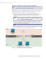
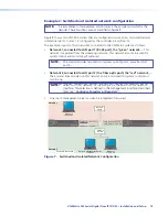
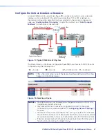
shows two VNC 325 codecs that are configured to work across two switched and
isolated networks. Codec 1 is configured as the controller, via LAN port 2.
This example consists of two networks, connected to the VN-Matrix system as follows:
•
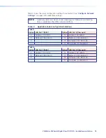
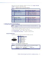
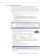
Network 1, connected to LAN port 1 (RJ-45 port), the “green” network
— This
network is separated from the streaming network. This network also can be used for
system control and monitoring if preferred.
NOTE:
The controller codec responds to inquiries on LAN port 1 as well as LAN
port 2.
•
Network 2, connected to LAN port 2 (the fiber optic port), the “red” network
—
The encoder streams video on this network and it is also used for system control and
monitoring.
NOTE:
Selection of this network for streaming is via the built-in HTML network
interface. This selection is defined in the management interface, described
later (see “
Configure Encoders or Decoders
“).
•
A network management server can also be integrated if required.
Network 1
Network 2
Network 2
Network 1
Optional Connections
VN-MATRIX 325 SERIES
SERIAL DIGITAL VIDEO OVER IP
LAN-1
LAN-2
STATUS
ALARM
TEST
VN-MATRIX 325 SERIES
SERIAL DIGITAL VIDEO OVER IP
LAN-1
LAN-2
STATUS
ALARM
TEST
Browser 2
192.168.0.3
Codec 1
Codec 2
Network Management Server
172.28.0.3
Browser 1
172.28.0.4
LAN Port 2:192.168.0.1
Controller
Network
Switch
Network
Switch
LAN Port 1:172.28.0.1
LAN Port 2:192.168.0.2
LAN Port 1:172.28.0.2
Figure 7.
Switched and Isolated Network Configuration
VN-Matrix 325 Serial Digital Over IP CODEC • Installation and Setup
13

