Configure the Units as Encoders or Decoders
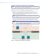
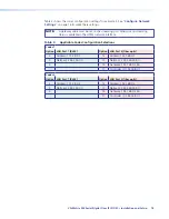
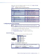
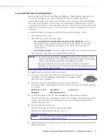
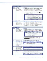
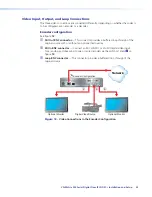
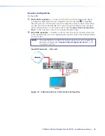
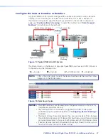
A typical VN-Matrix 325 network (see figure
17
) includes an encoder (source), a decoder
(display), and a controlling PC. The data transport method, TCP or RTP, is defined on
the decoder configuration page. Multicasting is selected on the encoder configuration
page (see “
Enable multicast streaming
“ to select the multicast and “
Data Transport
Methods
“ for definitions of the methods).
12V DC
3A MAX
POWER
LAN
1
2
OPTICAL
REMOTE
RS-232
OVER LAN
12V DC
3A MAX
POWER
LAN
1
2
OPTICAL
REMOTE
RS-232
OVER LAN
Optional
Local
Monitor
Monitor
Control and
Monitoring
Encoder Configuration
Encoded Video and Control
Decoder Configuration
Encoded Video
Decoded
Video
Digital Video Source
Network
Figure 17.
Typical VN-Matrix 325 System
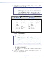
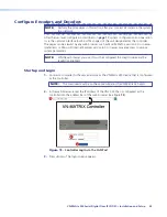
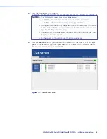
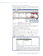
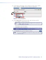
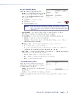
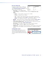
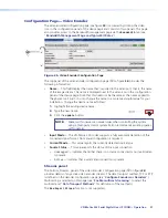
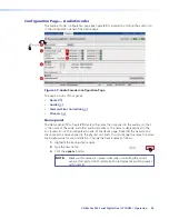
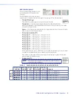
The Mode column on the Device List page (see figure
18
) shows how each VNC 325 unit is
configured using the following icons:
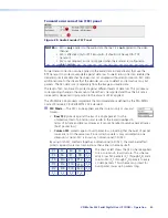
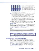
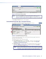
= Encoder
= Decoder
= VNM Recorder
= Undefined
NOTE:
If this is the initial setup, none of the devices have been defined and thus show
the icon in the Mode column.
1
Figure 18.
Selecting a Device
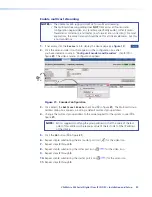
NOTES:
•
The VNM Recorder is not documented in this guide. Inclusion in this list is for
completeness and reference only.
•
Only devices that are or have been configured to connect to the system
controller (using the procedure detailed in “
Configuring Network Settings
“)
are listed.
•
The device list may show more devices than are in your system. This is because
the controller maintains a list of devices that have been used in the past and are
not currently available. In this case, the IP address entry for that device is blank.
•
If desired, remove devices that have been physically removed from the system
from this listing by clicking the Delete icon ( ).
VN-Matrix 325 Serial Digital Over IP CODEC • Installation and Setup
27

