XPA U 1004 SB and XPA U 2002 SB • Installation
6
e
XP
A U 100
4 SB
1
2
3
4
OV
ER
TEMP
LIMI
TER/PROT
ECT
SIGNAL
POWER
AMP
LIFI
ERS
e
XP
A U 100
4 SB
1
2
3
4
OV
ER
TEMP
LIMI
TER/PROT
ECT
SIGNAL
POW
ER
AM
PLIFI
ERS
Mounting
screws (4)
2
1
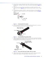
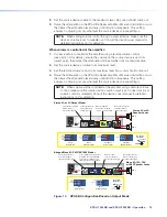
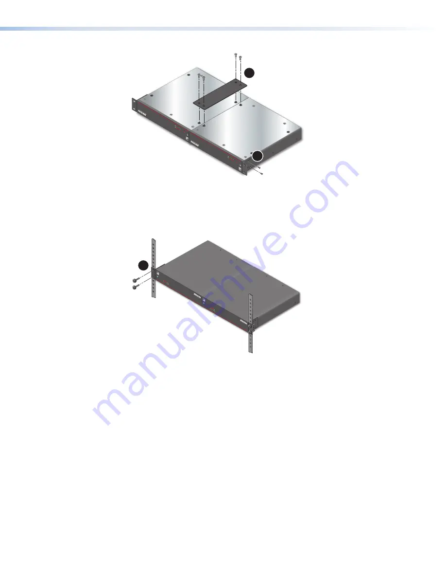
Figure 3.
Installing XPA Ultra Series Bridge Plate
5.
Insert the amplifiers into the rack and align the holes in the rack ears with the holes in
the rack.
6.
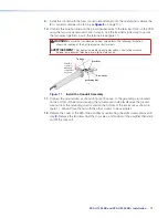
Secure the amplifiers to the rack using four provided 10-32 3/4” screws (see figure 4,
3
)
e
XP
A U 1004
SB
1
2
3
4
OVER
TEMP
LIMI
TER
/PRO
TECT
SIGNA
L
POW
ER A
MPLIFIE
RS
e
XP
A U 1004
SB
1
2
3
4
OVER
TEMP
LIMI
TER
/PRO
TECT
SIGNA
L
POW
ER A
MPLIFIE
RS
3
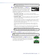
Figure 4.
Secure Connected XPA Ultra Amplifiers to Rack
Rack Shelf Mounting
The XPA U 1004 SB and XPA U 2002 SB can both be mounted in a shelf using the optional
RSU 129 1U Universal Rack Shelf Kit.
Mount the amplifier with the shelf as follows:
1.
If the rubber feet are installed on the bottom of the amplifier, remove them.
2.
Place the amplifier on one half of the rack shelf.
3.
Align the front of the amplifier with the front of the shelf, and align the threaded holes on
the bottom of the amplifier with the holes in the rack shelf.
4.
Attach the amplifier to the rack shelf with the two provided 4-40 x 3/16” machine
screws. Fasten them into diagonally opposite corners by inserting the screws from the
underside of the shelf.
5.
Either attach the false front panel, which is provided with the rack shelf, to the
unoccupied side of the rack, or install a second half rack-width device to that side.
Repeat steps 1 through 5 if a second device is being installed.
Summary of Contents for XPA U 1004 SB
Page 7: ......


