XPA U 1004 SB and XPA U 2002 SB • Installation
9
•
One 6 foot long electrical conduit
•
Three 7.5 foot, 18-gauge power wires with spade connectors
•
Three auxiliary crimp-style spade connectors designed for 14- to 16-gauge wires
•
One UL-rated zip tie wrap
The kit provides a way to replace the IEC power cord with a conduit, where required by
local codes.
NOTE:
If needed, Extron recommends using a UL-rated crimp tool to terminate the spade
connectors. One recommended choice is the Molex crimp tool.
UL Requirements
The Underwriters Laboratories (UL) requirements listed below pertain to the installation
of the flexible conduit onto an XPA U 1004 SB and XPA U 2002 SB.
•
This unit must not be used beyond its rated voltage range.
•
This unit must be wired to a UL-Listed distribution box.
NOTE:
The UL-approved electrical distribution box is not included with either the XPA
Ultra or the Flexible Conduit Adapter Kit. The installer is responsible for obtaining and
installing the box.
Installing the Flexible Conduit Adapter Kit
WARNING:
Electrostatic discharge (ESD) can damage IC chips even though you cannot feel
it. You must be electrically grounded before touching anything inside the XPA. A grounding
wrist strap is recommended.
AVERTISSEMENT :
Les décharges électrostatiques peuvent endommager les puces de circuit
même si vous ne pouvez pas les sentir. Vous devez être électriquement relié à la terre avant
de toucher un élément à l’intérieur du XPA. Un braceletde mise à la terreest recommandé.
Install the flexible conduit to the XPA Ultra Amplifier as follows:
1.
Unplug the IEC power cord from the amplifier.
2.
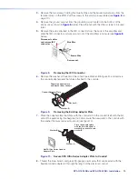
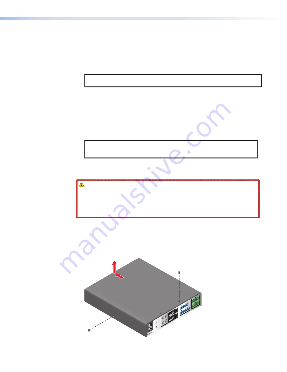
Remove the 8 screws from the top, sides, and bottom of the amplifier then slide and lift
the cover off.
BR
(
)
100
-24
0V
--A
, 50
-60
Hz
3
4
1
2
CL
ASS
2 W
IRING
0
2
4
6
8
10
∞
12
14
0
2
4
6
8
10
14
∞
12
2
4
3
0
2
4
6
8
10
14
18
26
∞
12
1
0
2
4
6
8
10
14
18
26
∞
12
1
2
3
4
G
G
C
V
G
C
V
ST
ANDB
Y
SIG
NA
L
1
SIG
NA
L
LIM
ITER
/
PROTEC
T
LIM
ITER
/
PR
OT
EC
T
2
3
4
AT
TE
NU
AT
ION
OU
TP
UT
MO
DE
INP
UT
S
RE
MOT
E
OU
TPU
TS
XPA
U
1004
SB
BR
BR
BR
(
)
1 &
2
3
BR
IDG
ED
MO
NO
70V
70V
HP
F O
FF)
100
V
100
V (H
PF
OFF
)
ST
ER
EO
& 4
8Ω
/4Ω
8Ω
8Ω
BR
IDG
ED
MO
NO
70V
70V
HP
F O
FF)
100
V
100
V (H
PF
OFF
)
ST
ER
EO
8Ω
/4Ω
8Ω
8Ω
3&
4
1&
2
Remove (8)
screws
Slide cover forward and
lift straight up.
Figure 7.
Removing the Cover
Summary of Contents for XPA U 1004 SB
Page 7: ......


