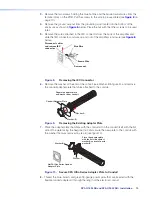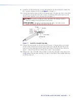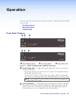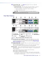
XPA U 1004 SB and XPA U 2002 SB • Operation
14
2.
Set the source device volume to the maximum level. No sound should come out.
3.
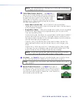
Raise the attenuation on the XPA Ultra Series amplifier until sound distortion occurs,
then lower the attenuation level slowly until distortion disappears. This setting
ensures no clipping occurs, whatever the source device volume setting is.
NOTE:
When setting volume control through a source device, make sure the
device’s volume is set to variable out. Consult the device’s user manual for
detailed instructions on its calibration.
When volume is controlled at the amplifier:
1.
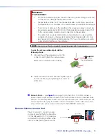
If volume will be controlled at the amplifier using a remote volume control
(see section G for details), ensure the volume on the source device is set to its
lowest point, then adjust the attenuation of the amplifier fully counterclockwise.
2.
Set the source device’s volume to its maximum level.
3.
Set the remote volume control to its maximum level. No sound should come out.
4.
Raise the attenuation on the XPA Ultra Series amplifier until sound distortion occurs,
then lower the attenuation level slowly until distortion disappears. This setting
ensures no clipping occurs, whatever the source device volume setting is.
NOTE:
When volume will be controlled at the amplifier using a remote volume
control, make sure the source device’s audio output is set to fixed out (local
volume control is disabled). Consult the device’s user manual for detailed
instructions on its calibration.
100-240V --A, 50-60 Hz
1
2
CLASS 2 WIRING
0
2
4
6
8
10
14
∞
12
2
1
0
2
4
6
8
10
14
18
26
∞
12
1
2
G
G
C
V
STANDBY
SIGNAL
1
LIMITER/
PROTECT
2
ATTENUATION
OUTPUT MODE
INPUTS
REMOTE
OUTPUTS
XPA U 2002 SB
BR
BR
(
)
1 & 2
BRIDGED
MONO
70V
70V (HPF OFF)
100V
100V (HPF OFF)
STEREO
4Ω
8Ω
8Ω
1&2
16Ω
Stereo
Balanced Input
Stereo
Unbalanced Input
Dual Mono
Balanced Input
Dual Mono
Unbalanced Input
Stereo 8Ω or 4Ω Output Modes
100-240V --A, 50-60 Hz
1
2
CLASS 2 WIRING
0
2
4
6
8
10
14
∞
12
2
1
0
2
4
6
8
10
14
18
26
∞
12
1
2
G
G
C
V
STANDBY
SIGNAL
1
LIMITER/
PROTECT
2
ATTENUATION
OUTPUT MODE
INPUTS
REMOTE
OUTPUTS
XPA U 2002 SB
BR
BR
(
)
1 & 2
BRIDGED
MONO
70V
70V (HPF OFF)
100V
100V (HPF OFF)
STEREO
4Ω
8Ω
8Ω
1&2
16Ω
Mono
Balanced Input
Mono
Unbalanced Input
Bridged Mono 8Ω/16Ω/70V/100V Modes
CH 2
CH 1
Stereo 8Ω or 4Ω
Speaker Loads
Mono 8Ω, 16Ω, 70V,
or 100V Speaker Loads
CH 1
Sleeves
" (5 mm) MAX.
3
16
Tip
Sleeves
Tip
Ring
Use CH 1 Attenuator to
set level for bridged
output (CH 2 is ignored)
Set Output Mode to appropriate
bridged mono setting (8Ω,16Ω,
70V, 100V). Use HPF OFF only
if HPF present in upstream DSP.
Wire CH 1 input
connector based on
source as shown below
Sleeves
Tip
Ring
Tip
Ring
Sleeves
Tip
Tip
Sleeves
Tip
Ring
Sleeves
Tip
Do not tin
the wires!
" (5 mm) MAX.
3
16
Do not tin
the wires!
Use both CH 1 and CH 2
Attenuators (set
levels independently)
Set Output Mode to
appropriate stereo
setting (8Ω or 4Ω)
Wire CH 1 and CH 2
input connector based
on source as shown below
Wire output connector
to speaker loads as
shown to the right
Wire output connector
to mono speaker load
as shown to the right
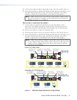
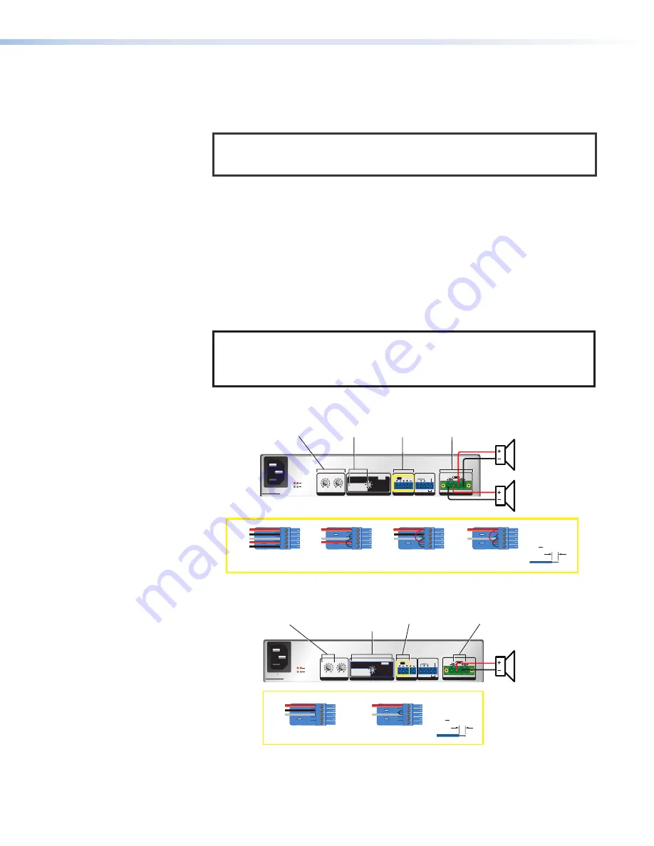
Figure 14.
XPA SB Configuration Based on Output Mode
Summary of Contents for XPA U 1004 SB
Page 7: ......


