background image

XPA U 1004 SB and XPA U 2002 SB • Operation

18

Troubleshooting

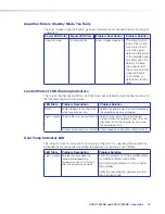
The front and rear panels have LED warning indicators, as described below.

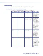
Amplifier Fails to Exit Standby Mode Promptly

The input channel signal LED lights green when an input signal is detected.

Power LED Color

Signal LED State

Problem Description

Problem Solution

Amber

Not lit

No output signal

No input detected, 
verify the input 
signal. If input signal 
is present, raise 
input  level until 
signal LED lights.

Green or Amber

Lit intermittently

Unit does not promptly 
exist standby mode when 
input signal is present

The output signal 
level of the source 
may be too low to 
cross the signal 
detection threshold 
of the amplifier (see 
amplifier specs for 
details). Increase 
the signal level of 
the source until the 
signal LED lights 
consistently, or 
defeat the standby 
timer.

Amber

Lit

No output signal

Ampilifer has been 
placed in standby 
mode and the 
output has been 
turned off. Check 
remote port. DC 
Fault may have 
been detected (see 
below). 

Amber

Lit

DC Fault is detected. Unit
does not exit standby.

Disconnect power 
then disconnect 
the remote port. 
Then, reconnect 
power to the unit to 
determine if the unit 
immediately goes 
into standby upon 
power up. In such 
a case, service the 
unit.

Summary of Contents for XPA U 1004 SB

Page 1: ...User Guide XPA U 1004 SB and XPA U 2002 SB XPA Ultra Series Half Rack Audio Power Amplifiers 68 3579 01 Rev A 02 21 ...

Page 2: ...tivas y seguridad de Extron referencia 68 290 01 en el sitio Web de Extron www extron com Instructions de sécurité Français AVERTISSEMENT Ce pictogramme lorsqu il est utilisé sur le produit signale à l utilisateur la présence à l intérieur du boîtier du produit d une tension électrique dangereuse susceptible de provoquer un choc électrique ATTENTION Ce pictogramme lorsqu il est utilisé sur le prod...

Page 3: ...com 의 Extron 안전 및 규제 준수 안내서 68 290 01 조항을 참조하십시오 Copyright 2021 Extron All rights reserved www extron com Trademarks All trademarks mentioned in this guide are the properties of their respective owners The following registered trademarks registered service marks SM and trademarks TM are the property of RGB Systems Inc or Extron see the current list of trademarks on the Terms of Use page at www ext...

Page 4: ... reception which can be determined by turning the equipment off and on you are encouraged to try to correct the interference by one or more of the following measures Reorient or relocate the receiving antenna Increase the separation between the equipment and receiver Connect the equipment into an outlet on a circuit different from that to which the receiver is connected Consult the dealer or an ex...

Page 5: ...k of property damage Risque de dommages matériels NOTE A note draws attention to important information TIP A tip provides a suggestion to make working with the application easier Specifications Availability Product specifications are available on the Extron website www extron com Extron Glossary of Terms A glossary of terms is available at http www extron com technology glossary aspx ...

Page 6: ...ack Mounting 5 Rack Ear Mounting 5 Bridge Plate Rack Mounting 6 Rack Shelf Mounting 7 Flexible Conduit Adapter Kit Installation 8 Operation 12 Front Panel Features 12 Rear Panel Features 13 Remote Standby Port 17 Troubleshooting 17 Amplifier Fails to Exit Standby Mode Promptly 17 Amplifier Enters Standby Mode Too Early 19 Limiter Protect LED Warning Indicators 19 Over Temp Indicator LED 19 Extron ...

Page 7: ......

Page 8: ...ble channel pairs that can drive 8 ohm 4 ohm 70 volt or 100 volt loads The XPA U 1004 SB s two individually bridgeable pairs can deliver two 100 watt channels into low impedance systems or one 200 watt channel into low or high impedance systems The XPA U 2002 SB s bridgeable output pair can deliver two 200 watt channels into low impedance systems or one 400 watt channel into low or high impedance ...

Page 9: ... quiet reliable operation The units generate substantially less heat than conventional power amplifiers making the XPA Ultra Series ideal for rack mount applications where space is limited See Rack Mounting Ventilation Recommendations on page 7 Defeatable auto standby with fast wake up The amplifiers meet ENERGY STAR qualification requirements with an auto standby feature that automatically places...

Page 10: ... Remote standby port Enables the XPA U 1004 SB and XPA U 2002 SB to be remotely powered down when not in use reducing operating cost Automatic clip limiter Detects actual onset of clipping Gain is automatically reduced without audible artifacts to prevent clipping distortion Multiple protection circuits Activate during output shorts thermal overload or DC faults to prevent damage to the amplifier ...

Page 11: ...safe installation of the equipment in a rack Elevated operating ambient temperature If the equipment is installed in a closed or multi unit rack assembly the operating ambient temperature of the rack environment may be greater than room ambient temperature Therefore install the equipment in an environment compatible with the maximum ambient temperature TMA 32 F to 122 F 0 C to 50 C 10 to 90 noncon...

Page 12: ...nsert the amplifier into the rack and align the holes in the rack ear with the holes on the rack 4 Secure the amplifier to the rack using four provided 10 32 x 3 4 screws see figure 2 2 e XP A U 10 04 SB 1 2 3 4 OV ER TEM P LIM ITE R P RO TEC T SIG NA L POW ER AM PLI FIE RS 2 Figure 2 Secure XPA Ultra Amplifier to Rack Bridge Plate Rack Mounting The XPA U 1004 SB and XPA U 2002 SB ships with a bri...

Page 13: ...lifiers to Rack Rack Shelf Mounting The XPA U 1004 SB and XPA U 2002 SB can both be mounted in a shelf using the optional RSU 129 1U Universal Rack Shelf Kit Mount the amplifier with the shelf as follows 1 If the rubber feet are installed on the bottom of the amplifier remove them 2 Place the amplifier on one half of the rack shelf 3 Align the front of the amplifier with the front of the shelf and...

Page 14: ...16 endommagera l unité et annulera la garantie Rack Mounting Ventilation Recommendations Excessive heat decreases the optimal lifetime of the power amplifier An Over Temp indicator LED on the front panel of the amplifier lights red whenever the recommended operating temperature has been exceeded The XPA Ultra amplifiers need to be arranged in a rack environment so that the environment around the a...

Page 15: ...rce before you begin Vérifiez que l appareil source et le périphérique source sont éteints et déconnectés de la source d alimentation avant de commencer To reduce the risk of fire or electric shock do not expose this apparatus to rain or moisture Afin de réduire les risques d incendie ou de choc électrique protégez cet appareil de la pluie ou de l humidité The product is a Class I product which mu...

Page 16: ...ischarge ESD can damage IC chips even though you cannot feel it You must be electrically grounded before touching anything inside the XPA A grounding wrist strap is recommended AVERTISSEMENT Les décharges électrostatiques peuvent endommager les puces de circuit même si vous ne pouvez pas les sentir Vous devez être électriquement relié à la terre avant de toucher un élément à l intérieur du XPA Un ...

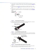
Page 17: ...C Connector 6 Remove the washer at the end of the conduit see Washer B in figure 9 and remove the conduit adapter plate that ships attached to the conduit Separate adapter plate and washer from conduit Washer B Washer A Conduit Adapter Plate Figure 9 Removing the Existing Adapter Plate 7 Place the adapter plate that ships with the conduit kit on the conduit itself with the flat side of the plate f...

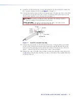
Page 18: ... la polarité correcte des câble L illustration suivante indique l emplacement des bornes de ligne et de neutre L N Slide IEC connector plate and conduit into enclosue 50 60H z 100 240V 1 3A Blue Wire Brown Wire Tie Wrap Grounding Nut Figure 11 Install the Conduit Assembly 11 Connect the ground wire as shown in figure 13 above to the grounding stud located on the bottom of the enclosure using the n...

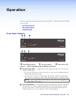
Page 19: ...t lights green when the unit is on and active and lights amber when The unit is in standby mode which turns off all outputs from the amplifier although the amplifier still receives power The unit will not come out of standby when DC voltage is detected The amplifier only comes out of standby mode by either resetting the device or powering it down NOTE Power indicator LED may stay lit amber for a s...

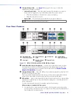
Page 20: ...2 SB BR BR 1 2 BRIDGED MONO 70V 70V HPF OFF 100V 100V HPF OFF STEREO 4Ω 8Ω 8Ω 1 2 16Ω A B D E G F C A B D E G F C A Removable IEC Power Receptacle B Channel Status LEDs C Attenuators D Output Mode Selector Switches E Line Input F Speaker Output Connectors G Remote Ports Figure 13 XPA U 1004 SB and XPA U 2002 SB Rear Panels A Removable IEC Power Receptacle Connect the supplied IEC power cord here f...

Page 21: ...tructions on its calibration 100 240V A 50 60 Hz 1 2 CLASS 2 WIRING 0 2 4 6 8 10 14 12 2 1 0 2 4 6 8 10 14 18 26 12 1 2 G G C V STANDBY SIGNAL 1 LIMITER PROTECT 2 ATTENUATION OUTPUT MODE INPUTS REMOTE OUTPUTS XPA U 2002 SB BR BR 1 2 BRIDGED MONO 70V 70V HPF OFF 100V 100V HPF OFF STEREO 4Ω 8Ω 8Ω 1 2 16Ω Stereo Balanced Input Stereo Unbalanced Input Dual Mono Balanced Input Dual Mono Unbalanced Inpu...

Page 22: ... channel s pin And the higher numbered output s positive pin becomes the bridged output s negative pin The level is set by using the attenuator on the lowest numbered channel The higher numbered channel s input and attenuator are not used in bridged mono mode In either 70V or 100V modes an 80 Hz 12 dB octave high pass filter is applied to the signal This can be disabled by selecting HPF OFF for ei...

Page 23: ...utput to comply with UL requirements To wire the stereo audio output do the following steps 1 Strip and insert the speaker wires into the connector and tighten the captive screws Make sure to observe correct polarity 2 Insert the wired connector into the amplifier output and secure the plug by tightening the screws on either side G Remote Ports see figure 14 on page 14 On the XPA U 1004 SB connect...

Page 24: ...uded 3 5 mm 2 pole captive screw connector to remotely ground the Standby pin The power indicator LED lights amber when the amplifier is in standby mode STANDBY G REMOTE G C V 1 REMO G C V 1 S O Ground Standby Figure 16 Remote Standby Port The amplifier will automatically enter standby mode after 25 minutes of inactivity from a loss of signal The inactivity timer can be disabled by wiring a 10 kΩ ...

Page 25: ...t promptly exist standby mode when input signal is present The output signal level of the source may be too low to cross the signal detection threshold of the amplifier see amplifier specs for details Increase the signal level of the source until the signal LED lights consistently or defeat the standby timer Amber Lit No output signal Ampilifer has been placed in standby mode and the output has be...

Page 26: ...Audio clipping is occurring at the rate of one blink per clip Reduce the power output to avoid overdriving the amplifier and causing clipping Lights steadily The amplifier may be overheating Determine the reason for the overheated state and allow the amplifier to cool The LED will not be lit after the amplifier recovers from the overheated state Output channel leads are shorted Check speakers and ...

Page 27: ...South Tower 160 Jan Smuts Avenue Rosebank 2196 South Africa This Limited Warranty does not apply if the fault has been caused by misuse improper handling care electrical or mechanical abuse abnormal operating conditions or if modifications were made to the product that were not authorized by Extron NOTE If a product is defective please call Extron and ask for an Application Engineer to receive an ...

Reviews: