background image


 @ Eye Trax, Inc All Rights Reserved  


             Page 21 of 27 

Cellular 
Connectivity 

Signal Strength 

Install The Antenna 

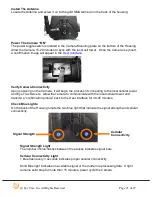
Locate the Antenna and screw it on to the gold SMA terminal on the back of the housing. 


Power The Camera “ON” 

The power toggle switch is located in the Camera Mounting plate on the bottom of the Housing.  
Allow the Camera 15-20 minutes to sync with the local cell tower.  Once the Camera is synced, 
a confirmation image will appear in the 

User Interface


Verify Camera Connectivity 

Upon powering on the Camera, it will begin the process of connecting to the local cellular tower 
and Eye Trax Servers.  Allow the camera to communicate with the local cellular tower and 
transmit a “confirmation picture” back to the User Interface for 30-45 minutes. 

 
Check Blue Lights 

On the back of the Housing locate the two blue light that indicate the signal strength and cellular 
connectivity. 


Signal Strength Light 


The number of blue flashes between the pauses indicates signal bars. 


Cellular Connectivity Light 


1 blue flash every 3 seconds indicates proper cellular connectivity. 


Solid Blue light indicates no available signal or the modem is processing data.  If light 


remains solid blue for more than 15 minutes, power cycle the Camera.  


Summary of Contents for Ranger 110V

Page 1: ...Eye Trax Inc All Rights Reserved Page 1 of 27 Eye Trax Inc User Guide Ranger Solar 110V Version 8 15...

Page 2: ...and Password to access the User Interface and is the Administrator on the account http www eyetrax net The cellular provisioning was pre configured based on the initial deploy location of the camera d...

Page 3: ...e Antenna Step 2 Power the camera ON by depressing the toggle switch located within the Camera s mounting plate Step 4 Allow the camera to communicate with the local cellular tower and transmit a conf...

Page 4: ...will appear The Camera Console is designed to be the command center for viewing all outdoor cameras and having quick controls for changing settings for all wireless outdoor security cameras and Users...

Page 5: ...le Play Step 1 Click on Member Login Step 2 Enter username and password This information was emailed to the Purchaser of the camera system along with the tracking number of the shipment Camera Console...

Page 6: ...sent over the cellular network prior to acquiring additional Burst of pictures Cellular transmission speed varies on available bandwidth The time that is stamped on each picture is the time for which...

Page 7: ...lick on Add New Location to create a physical location for the camera system This will allow the cameras to be mapped for a location reference NOTE Moving a camera from one location to a new one will...

Page 8: ...ne will remove all of the pictures associated with the camera and location Manage Users Click the Manage Users icon to create modify set administrative privileges and reset passwords for Users The ori...

Page 9: ...view the User Interface without the permission to make any changes to camera acquisition settings No Access no access to the see the camera in login Delete Pictures Click the Delete Photos button to...

Page 10: ...the camera If a User clicks on this image it will open the User Interface and allow that User to view pictures and features but not have the ability to alter any settings Once the User has clicked on...

Page 11: ...harging the battery see Solar Panel Installation page 22 or the picture acquisition rate is higher than the charging system can handle given ranging climate changes and solar exposure a WARNING email...

Page 12: ...e NOTE This command must be sent to the camera every time it is moved to a new location in order to establish communication with the local cellular tower NOTE While the camera is in 5 Picture Burst mo...

Page 13: ...a live photo returning to the User Interface in 90 seconds or less Email Notification This feature allows a User to send the picture in the viewing area via email Mobile Phone MMS Notification This f...

Page 14: ...to view all pictures acquired by the camera and create a time lapse video By choosing different days or one single day on the calendar drop down menus a low resolution time lapse video preview is crea...

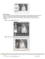
Page 15: ...quired pictures by using the notes feature The notes can be saved for other Users to add to with additional comments and drawings All notes are stored in the User Interface s picture archive or saved...

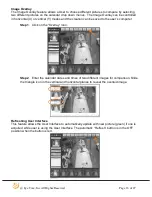
Page 16: ...eation can be saved to the user s computer Step 1 Click on the Overlay icon Step 2 Enter the calendar dates and times of two different images for comparison Slide the triangle icon in the vertical and...

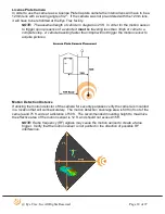
Page 17: ...point If using the Motion Sensor for security camera purposes note that it has an effective distance of 50 ft in front of viewing area Identify Mounting Location The standard lens installed on the cam...

Page 18: ...e to a complete stop A vehicle traveling faster than 3mph will not trigger the motion sensor to acquire pictures Motion Detection Distance If utilizing the motion detector of the camera for security p...

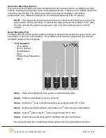
Page 19: ...n wires in 50 ft lengths Barrel Mounting Pole The Barrel Mounting Pole system patent pending is designed for locations where security and surveillance is done in short durations Once Barrel is full of...

Page 20: ...ed concrete into hole and tamp with shovel to remove trapped air Step 3 Place previously removed soil back into hole and compact by stomping on soil with foot Step 4 Check the vertical straightness on...

Page 21: ...a it will begin the process of connecting to the local cellular tower and Eye Trax Servers Allow the camera to communicate with the local cellular tower and transmit a confirmation picture back to the...

Page 22: ...Camera onto the Mounting Bracket so that the Thumb Screw slides thru the slot on the Bracket mounting face Step 2 Install the x 20 pan head screw with a Philips Head Screw driver in the remaining slot...

Page 23: ...and the Eye Trax Servers This step MUST be done every time the camera is relocated to new deploy locations Step 5 Verify the aiming of the camera by analyzing newly acquired picture in User Interface...

Page 24: ...ins the Solar Panel Step 7 Tighten both x 20 pan head screws to secure the Solar Panel to the Mounting Bracket Aim The Solar Panel The solar panel keeps the internal batteries inside the camera housin...

Page 25: ...e safety regulations NOTE During power loss the camera will not function Adjust The Motion Sensor If needed adjust motion detector so that it is square with camera housing and pointing in the same dir...

Page 26: ...k ON This will re sync the cellular modem with the cellular network Step 2 Send picture acquisition settings to the camera by selecting the Settings icon By sending these commands the local cellular t...

Page 27: ...ency is not triggering the motion sensor including radios cellular phones wireless networks etc Step 3 Power cycle camera by turning it OFF for 60 seconds and then back ON Motion Detector Is Not Trigg...

Reviews: