- 8 -
eyeheight
eyeheight
eyeheight
eyeheight
Unit 34 Park House Watford Business Park Greenhill Crescent Watford Herts GB WD18 8PH
Reg. No. 2855535 Telephone: +44 (0) 1923 256 000 Fax: +44 (0) 1923 256 100 email: eesales@eyeheight.com
2.4
2.4
2.4
2.4 Connecting Panels to the NS
Connecting Panels to the NS
Connecting Panels to the NS
Connecting Panels to the NS----41
41
41
41
The NS-41 may be operated using a FP-9 or FP-10 Flexipanel locally, or
remotely mounted. For detailed information on connecting remote panels refer to
the section “Connection of Remote Panels to a flexiBox” in the geNETics
Hardware Installation Guide.
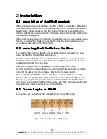
Below is shown a typical system consisting of an NS-41 in a flexiBox controlled
by an FP-9.
Connect Pins 1,2,4,7,9 from chassis to
panels (1:1). Use twisted pair AES
Digital Audio cable for pins 2 and 7. Pins
1,4,9 carry power 0.5 Amp, 13V. Use
cable with a least a 1 amp rating for pins
1,4,9. Cable llength should not exceed
250m.
I-Bus pins 2 & 7
**
**
** The I-BUS Network requires terminating with 100 Ohms at each extreme end of the network. Ensure that this is
done either by an external 100 ohm resistor OR ONE Panel/Product at each end has the termination set. See the
"Genetics User Guide" Under the sections "Flexipanel Power/I-BUS Jumpers".For the 4RU Panels see “4RU
Panel (FP-10) Jumpers for I-BUS” and “4RU Panel (VP-10, SW-10, AP-10) Jumpers for I-BUS” . Alternatively The
termination can be set on a Product (ie the AS-2 module). Information about this is given in this manual.
N.B. From 1/10/02, Eyeheight introduced a change in the flexiBox Chassis. Most
versions now have two 9 way connectors on the rear labelled “I-Bus” and “D-
Bus”. The “I-Bus” connector is the same as the previously labelled “Can-B”
connector. Although a maxiBox is shown in this diagram the same, arrangement
applies for a flexiBox chassis.

