PATHWAY HD Code Compliant Modular Access System Installation Manual
Page 89 of 92
7.4.
RAMP TRANSITION PLATE
7.4.1.
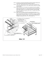
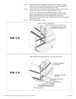
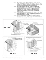
48”, 54”, and 60” ramp transition plates, in combination with a ramp support, are
commonly used to span wider gaps or accommodate angular misalignment. The ramp
transition plate can be used at either end of a ramp or ramp run.
The ramp transition plate will not support the end of a ramp or ramp run
without a ramp support.
The ramp transition plate, with a ramp support, can be used instead of the
ramp hanger pair, if desired. In some situations, it can also be used when
transitioning from a ramp to an existing porch or deck or when transitioning to
the ground instead of the starter ramp.
7.4.2.
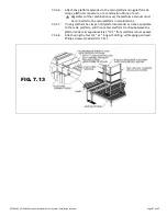
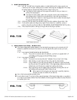
Lift the end of the ramp and install the ramp transition plate as shown (FIG. 7.15).
7.4.3.
If a transition plate is resting on any type of raised area (i.e. a platform, deck, or
porch), it must be anchored. Refer to ‘ANCHORING RAMP TRANSITION PLATE’ section.
7.4.4.
If the transition plate is resting on the ground, anchoring is optional.
FIG. 7.15
7.5.
SINGLE BRIDGE PLATE (TBPxx - BRIDGE PLATE)
The single bridge plate (bridge plate) is only intended to span gaps up to a maximum of 6”
between a platform and a porch or deck; it is not intended to be used as a ramp or on an
incline.
7.5.1.
Securing to WOODEN SURFACE OR PLATFORM:
7.5.1.1.
To secure to a wooden deck or platform, use the four supplied 1/4″ x 1″
self-drilling, self-tapping pan head Phillips screws.
7.5.2.
Securing to CONCRETE:
7.5.2.1.
To secure to concrete, drill
a 1/4″ diameter hole at least 1
-1/2
″
deep.
7.5.2.2.
After drilling, ensure holes are free of any dust or other debris.
7.5.2.3.
Using a
hammer, drive the two provided 1/4″ diameter mushroom head
pin drive anchors through the holes in the single bridge plate and into the
drilled holes until the head is seated flush with anchor body.
7.5.2.4.
Attach the other side of bridge plate
to the platform using the 1/4″ x 1″
self-drilling self-tapping pan head Phillips screws.
Other types of anchoring devices may work in specific situations;
contact your local contractor for assistance.
Use in the horizontal (flat) position only.
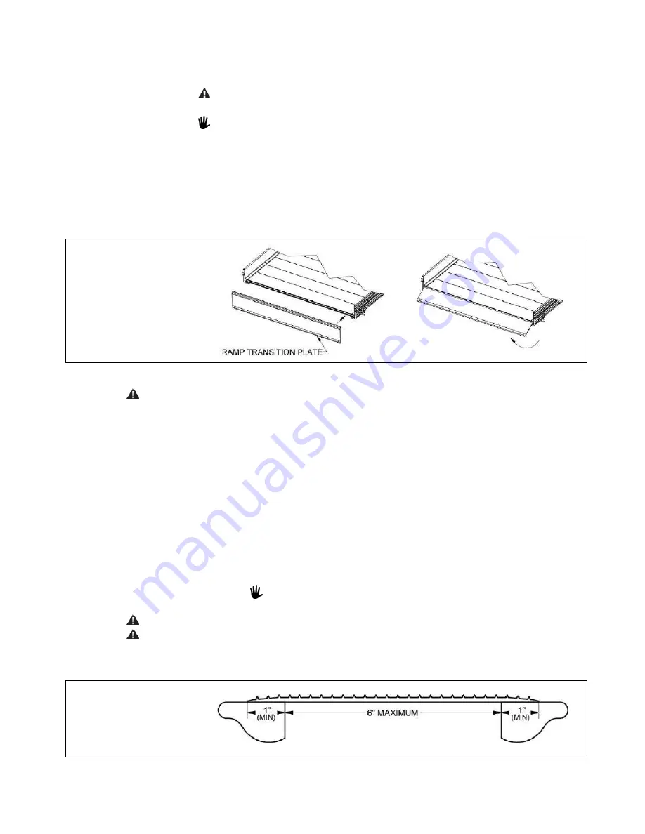
Ensure that at least 1” on each of the supporting edges of the single bridge plate is supported
on a level, sound surface that is free from defects and can support the same structural loads as
the system (FIG 7.16).
FIG. 7.16


