background image

ST 4X4

GASOLINE POWERED 4 WHEEL DRIVE 

UTILITY VEHICLE

STARTING MODEL YEAR: 2004

TECHNICIAN’S

REPAIR AND SERVICE MANUAL

600392

Ref Fcv 19 

Summary of Contents for ST 4X4

Page 1: ...ST 4X4 GASOLINE POWERED 4 WHEEL DRIVE UTILITY VEHICLE STARTING MODEL YEAR 2004 TECHNICIAN S REPAIR AND SERVICE MANUAL 600392 Ref Fcv 19...

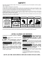
Page 2: ...rouilleur du Canada Read and understand all labels located on the vehicle For any questions on any of the information contact a represen tative for clarification Always replace any damaged or missing...

Page 3: ...the informa tion contained in this manual is subject to change without notice E Z GO Division of Textron Inc is not liable for errors in this manual or for incidental or consequential damages that re...

Page 4: ...adjusting the governor to permit vehicle to operate at above factory specifications will void the vehicle warranty When servicing engines all adjustments and replacement components must be per origina...

Page 5: ...Routine Maintenance A Safety B Body and Truckbed C Brakes D Continuously Variable Transmission CVT E Direction and Drive Selector F Electrical G Engine and Transmission H Front Suspension and Steering...

Page 6: ...Page iv Repair and Service Manual TABLE OF CONTENTS Notes...

Page 7: ...f the material in this manual This vehicle conforms to the current applicable standard s for safety and performance requirements These vehicles are designed and manufactured for off road use They do n...

Page 8: ...that tools and procedures not specifically recommended by the manufacturer will not compromise the safety of personnel nor jeopardize the safe operation of the vehicle Support the vehicle using wheel...

Page 9: ...om accumulating Never fuel a vehicle in an area that is subject to flame or spark Pay particular attention to natural gas or propane water heaters and furnaces Never work around or operate a vehicle i...

Page 10: ...Repair and Service Manual SAFETY INFORMATION Page viii Notes...

Page 11: ...POSITION A 3 BRAKES A 4 TIRES A 4 CARE AND CLEANING OF THE VEHICLE A 4 VEHICLE CARE PRODUCTS A 4 TOP AND WINDSHIELD IF EQUIPPED A 5 TRAILERING A 5 PROLONGED STORAGE A 5 HARDWARE A 6 TORQUE SPECIFICAT...

Page 12: ...GENERAL INFORMATION ROUTINE MAINTENANCE Page A ii Repair and Service Manual Notes...

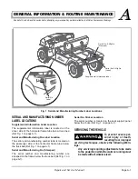
Page 13: ...bed Ref Fig 1 on page A 1 Serial and Manufacturing No Stamped The serial number and manufacturing number are stamped on the frame below the truck bed Ref Fig 1 on page A 1 Serial No Sticker Location T...

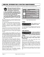
Page 14: ...heavy spring loaded highly cor rosive explosive may produce amperage or reach high temperatures Gasoline carbon monoxide battery acid and hydrogen gas could result in serious bodily injury to the tech...

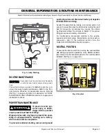
Page 15: ...a dropped wrench shorting out a battery which could result in an explosion To prevent accidental starting remove and ground spark plug wires and disconnect battery at negative terminal before servicin...

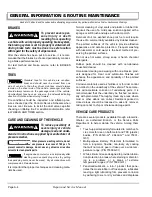
Page 16: ...g mate rials be used Normal cleaning of vinyl seats and plastic or rubber trim requires the use of a mild soap solution applied with a sponge or soft brush and wipe with a damp cloth Removal of oil ta...

Page 17: ...ts are adequately secured before trailering the vehicle The rated capacity of the trailer must exceed the weight of the vehicle see GENERAL SPECIFICATIONS for vehicle weight and load Engage the parkin...

Page 18: ...over a few seconds to distribute oil Clean body chassis and engine of debris mud chaff or grass See ENGINE section HARDWARE Periodically the vehicle should be inspected for loose fasteners Fasteners...

Page 19: ...wet and require approximately 80 of the torque required for dry fasteners 4 5 8 11 15 20 24 33 35 47 55 75 75 102 130 176 125 169 190 258 Grade 5 Grade 8 6 8 13 18 23 31 35 47 55 75 80 108 110 149 200...

Page 20: ...pect X Rotors Drums Clean X Park Brake Clean X X Reverse Warning Buzzer if equipped Check X Tires Check X X Overall Vehicle Condition Check X Wheels Check X Fuel Gauge Check X Alternator Belt Check X...

Page 21: ...EVERY 300 HOURS EVERY 500 HOURS Tie Rods Linkages Check X Rear Axle Lubricant Check X X Replace X X Front Axle Lubricant Check X X Replace X X Transmission Transfer Case Lubricant Check X X Replace X...

Page 22: ...L INFORMATION ROUTINE MAINTENANCE Page A 10 Repair and Service Manual Read all of Section B and this section before attempting any procedure Pay particular attention to all Notes Cautions and Warnings...

Page 23: ...LIST OF ILLUSTRATIONS GENERAL B 1 NOTES CAUTIONS AND WARNINGS B 5 IMPORTANT SAFETY WARNING B 5 MODIFICATIONS TO VEHICLE B 5 GENERAL MAINTENANCE B 5 BEFORE SERVICING THE VEHICLE B 6 BATTERY REMOVAL AND...

Page 24: ...SAFETY Page B ii Repair and Service Manual Notes...

Page 25: ...trians and vehicle operators of traffic conditions and to use cau tion B 1 1 1 4 The controlling party shall train vehicle operators to adhere strictly to the operating instructions stated in vehicle...

Page 26: ...ocks B 1 1 8 1 The controlling party shall make periodic inspections of the vehicle to be certain that the safety interlock system if so equipped is operating properly B 2 Operating Safety Rules and P...

Page 27: ...void loads which cannot be centered B 2 4 3 Transport only loads within the gross vehicle weight capacity B 2 4 4 Avoid material loads exceeding the physical dimensions of the vehicle or as specified...

Page 28: ...esigned and approved for hazardous area operation shall be inspected to ensure that maintenance preserves the original approved oper ating features n Fuel systems shall be checked for leaks and condi...

Page 29: ...f the component should move unex pectedly Some components are heavy spring loaded highly cor rosive explosive or may produce high amperage or reach high temperatures Gasoline carbon monoxide battery a...

Page 30: ...operate the starter with the spark plugs removed unless the ignition system has been dis abled and the engine exhaust are cold Fuel expelled from the cylinders could be ignited by the ignition system...

Page 31: ...on A Tool List Qty Required Ratchet 3 8 drive 1 Torque wrench 3 8 drive ft lbs 1 Extension 12 3 8 drive 1 Socket 1 2 3 8 drive 1 Insulated wrench 1 2 1 Battery carrier 1 Turn vehicle key OFF and remov...

Page 32: ...4 Some servicing operations may require the front rear or the entire vehicle to be raised To raise the entire vehicle install chocks in front and behind each front wheel Ref Fig 2 on page B 8 Center...

Page 33: ...Panel Replacement C 12 Front Fender Well Replacement C 12 LIST OF ILLUSTRATIONS Fig 1 Seat Bottom Replacement C 1 Fig 2 Seat Back Replacement C 1 Fig 3 Gas Spring Replacement C 2 Fig 4 Light Guard Si...

Page 34: ...BODY AND TRUCKBED Page C ii Repair and Service Manual Notes...

Page 35: ...Release the truck bed handle and raise the bed Ref Fig 2 on page C 1 Remove the screws item 1 and the washers item 2 securing the seat back to the cover plate item 3 using Phillips screwdriver Remove...

Page 36: ...1 Park vehicle on a level surface Engage park brake Hold the bolts item 1 using a 9 16 socket and remove the nuts item 2 using a 9 16 wrench Ref Fig 4 on page C 3 Remove the washers item 3 Use an ass...

Page 37: ...help to remove the front brush guard item 4 carefully from the vehicle Installation of front brush guard is the reverse of disas sembly using new lock nuts Tighten the hardware per torque specificatio...

Page 38: ...socket and remove the nuts item 2 using 3 4 wrench Ref Fig 7 on page C 4 Remove washers item 3 Remove the bolts item 1 and the backing plates item 4 Lower the receiver item 5 and move through the driv...

Page 39: ...is the reverse of disassembly Cowl Replacement 6Q RTGXGPV UGXGTG RGT UQPCN KPLWT QT FGCVJ TGUWNVKPI HTQO GZRNQUKQP ECWUGF D CP GNGEVTKECN CTE DG UWTG VJCV VJG MG UYKVEJ KU QHH CPF CNN GNGEVTKECN CEEGU...

Page 40: ...Refer Battery Removal and Installation in SAFETY Separate the head light plugs and receptacles Refer ELECTRICAL for head light replacement Remove all the wiring connected to instru ment panel and note...

Page 41: ...YTGPEJGU YKVJ XKP N VCRG VQ RTGXGPV VJG RQUUKDKNKV QH C FTQRRGF YTGPEJ HTQO UJQTVKPI QWV VJG DCVVGT YJKEJ EQWNF TGUWNV KP CP GZRNQUKQP CPF UGXGTG RGT UQPCN KPLWT QT FGCVJ 6JG DCVVGT PGICVKXG ECDNG OW...

Page 42: ...16 1 Phillips head screwdriver 1 Park vehicle on a level surface Engage park brake Hold the bolts item 1 using Phillips head screwdriver and remove the nuts item 2 using 7 16 wrench Ref Fig 12 on page...

Page 43: ...the bed Remove the screws item 2 using Phillips head screwdriver Ref Fig 14 on page C 9 Remove the fuel cap item 1 Remove the seat panel passenger side item 3 from fuel tank neck Replace the fuel cap...

Page 44: ...rk vehicle on a level surface Engage park brake Remove rocker panel Ref Rocker Panel Replacement Section on page C 8 Remove the floorpan Ref Floor pan Replacement Section on page C 8 Remove the riv et...

Page 45: ...se truck bed handle and lift the bed Remove the ratchet fasteners item 1 from the top of rear fender Ref Fig 18 on page C 11 Hold the screws item 2 using 3 8 wrench and remove the nut item 3 using 7 1...

Page 46: ...NG 6Q RTGXGPV UGTKQWU RGTUQPCN KPLWT QT FGCVJ TGUWNVKPI HTQO GZRNQUKQP ECWUGF D CP GNGEVTKECN CTE DG UWTG VJCV VJG MG UYKVEJ KU QHH CPF CNN GNGEVTKECN CEEGUUQTKGU CTG VWTPGF QHH DGHQTG UVCTVKPI YQTM Q...

Page 47: ...Hold the bolt item 2 connecting upper mount frame to the main frame using 9 16 wrench and remove the nut item 3 using 9 16 socket Ref Fig 21 on page C 14 Remove the bolt item 4 using 13mm wrench and w...

Page 48: ...GRCKT CPF 5GTXKEG CPWCN 4GCF CNN QH 5GEVKQP CPF VJKU UGEVKQP DGHQTG CVVGORVKPI CP RTQEGFWTG 2C RCTVKEWNCT CVVGPVKQP VQ CNN 0QVGU CWVKQPU CPF 9CTPKPIU Fig 21 Front Fender Well Replacement 6 8 10 12 11...

Page 49: ...rake Rotor Replacement D 11 BLEEDING AND FLUSHING D 11 Bleeding D 11 Bleeding Sequence D 12 Flushing D 12 BRAKE PEDAL REPLACEMENT D 13 PARKING BRAKE D 13 Lubrication D 13 Adjustment D 13 Cable Replace...

Page 50: ...BRAKES Page D ii Repair and Service Manual Notes...

Page 51: ...l Notes Cautions and Warnings Fig 1 Hydraulic Brake System Components Brake Pedal Extension Spring Clevis Yoke Rotor Rear Brake Line Mounts To Frame Mounts To Frame Mounts To Frame Front Brake Line Br...

Page 52: ...The wheel cylinders are a double piston design providing even distribution of force to each shoe There are no links Shoes rest directly on the piston ends Wheel cylinders incorporate external boots B...

Page 53: ...in braking effect from the friction material being worn away a loss of braking at one wheel or a sudden and complete failure with no brakes working except the park ing brake Should the brakes at one w...

Page 54: ...Flushing section During this process it is likely that brake fluid will leak from the master cyl inder Avoid allowing brake fluid to contact the painted body components of the vehicle Wipe off immedia...

Page 55: ...m 1 Remove the master cylinder item 1 from the vehicle Installation of a new master cylinder is the reverse of dis assembly using new lock nuts Reconnect and tighten the brake lines items 2 3 per torq...

Page 56: ...ll the brake drum slide the brake drum into place WHEEL BRAKE SERVICE AND REPLACEMENT To prevent dust inhala tion or eye injury always wear a dust mask and eye protection whenever working on wheel bra...

Page 57: ...bolts item 6 from the rear axle item 7 flange using a 1 2 wrench and remove it using 1 2 socket and extension Pull the brake assembly item 8 and rear axle shaft item 9 out from the axle tube item 7 a...

Page 58: ...djusters are frozen badly worn or loose replace the adjuster assembly Replace the wheel cylinder item 14 if there is any sign of leakage Insure that the parking lever and strut assem bly moves freely...

Page 59: ...and reverse stops by applying firm pressure to the brake pedal on each stop to bring shoes to proper adjust ment FRONT DISC BRAKE REPLACEMENT To prevent dust inhala tion or eye injury always wear a du...

Page 60: ...Torque wrench 1 2 drive 165 ft lbs capacity 1 Impact socket 3 4 1 2 drive 1 Allen wrench 9 mm 3 8 drive 1 Needle nose pliers 1 Park the vehicle on a level surface engage park brake Loosen the four nut...

Page 61: ...of the disc brake rotor is the reverse of disas sembly Tighten the wheel lug nuts to 50 85 ft lbs 70 115 Nm torque in 20 ft lbs 30 Nm increments BLEEDING AND FLUSHING Tool List Qty Required Torque wr...

Page 62: ...linder reservoir and wheel cylinder bleeder valves Clean each fitting before opening to prevent contaminating the system Fill master cylinder reservoir to the maximum level with new brake fluid before...

Page 63: ...item 4 back so that clevis yoke item 5 will come out of master cylinder item 6 Inspect the shoulder bolt item 2 for corrosion that could cause binding This bolt and both bushings item 7 must be repla...

Page 64: ...k the tension see that the cable is straight Correct tension is when at the sixth click of the hand operated parking brake lever the vehicle will not move while under a load on a typical area slope Re...

Page 65: ...tie securing the rubber boot to the parking brake item 1 Remove the boot Remove the nut item 6 and spherical nut item 7 Remove cotter pin and clevis pin item 2 and pull cable item 4 free Check to see...

Page 66: ...BRAKES Page D 16 Repair and Service Manual Read all of Section B and this section before attempting any procedure Pay particular attention to all Notes Cautions and Warnings Notes...

Page 67: ...S E 1 Drive Clutch E 1 Driven Clutch E 1 Increased Load E 2 Equilibrium E 2 Drive Clutch Replacement E 2 Driven Clutch Replacement E 3 DRIVE BELT E 4 Removing the Drive Belt E 4 Drive Belt Service E 4...

Page 68: ...CONTINUOUSLY VARIABLE TRANSMISSION CVT Page E ii Repair and Service Manual Notes...

Page 69: ...er of the drive clutch sheaves which increases the speed of the belt As the drive clutch sheaves close the driven clutch sheaves are forced open by the belt as it rises in the drive clutch The ratio i...

Page 70: ...inadvert ant movement of the vehicle Disable the electrical system before attempting to remove the drive belt to prevent the engine from inadvertently starting Do not allow fingers to become trapped...

Page 71: ...e the bolt item 1 and remove the CVT cover item 2 Remove the drive belt item 3 Ref Removing the Drive Belt section on page E 4 Remove the driven clutch bolt item 8 using 1 2 socket lock washer item 9...

Page 72: ...en be rolled off the driven clutch Drive Belt Service The drive belt will require no service unless the vehicle has been operated in an extremely dusty or muddy loca tion in which case it should be wa...

Page 73: ...ector Replacement F 3 DRIVE SELECTOR F 3 Drive Selector Replacement F 3 Proximity Sensor Switch Replacement F 4 LIST OF ILLUSTRATIONS Fig 1 Direction Drive Selector Components F 1 Fig 2 Direction Driv...

Page 74: ...DIRECTION AND DRIVE SELECTOR Page F ii Repair and Service Manual Notes...

Page 75: ...ention to all Notes Cautions and Warnings Fig 1 Direction Drive Selector Components Levers On Transmission Transfer Case Shifter Housing Direction Selector Cable Drive Selector Cable Proximity Sensor...

Page 76: ...nd Drive Selector Cables Adjust ment Failure of the transmission to engage correctly indicates that cable adjustment is required Tool List Qty Required Open end wrench 15 16 Direction selector 2 Open...

Page 77: ...selector bracket item 5 to the shifter housing item 6 from back side of dash Remove direction selector cable item 7 Ref Direction And Drive Selector Cables Adjustment Section on page F 2 Remove the d...

Page 78: ...arate the wire harness at the sensor Move the drive control to the 4 wheel drive position Ref Fig 6 on page F 4 Select the audible continuity setting on the DVOM Insert the two DVOM test probes into t...

Page 79: ...TING G 6 POWER SUPPLY G 6 ACCESSORY WIRING G 7 INSTRUMENT CLUSTER G 7 DIFFERENTIAL LOCK SOLENOIDS G 7 FUEL CUT SOLENOID G 8 NEUTRAL SWITCH G 8 HEADLIGHTS G 8 TAILLIGHT ACCESSORY G 8 BRAKE SWITCH G 8 P...

Page 80: ...ELECTRICAL Page G ii Repair and Service Manual Notes...

Page 81: ...GHT HEADLT TAIL LIGHT BRAKE LIGHT PWR OUTLET PARK BRAKE SWITCH KEY SWITCH 25 AMP IN LINE FUSE OIL LIGHT SWITCH FUEL SENDING SWITCH LIGHT SWITCH BRAKE LIGHT SWITCH ENGINE STOP DIODE REGULATOR RECTIFIER...

Page 82: ...s closed and will operate the starter if the neutral switch is in the closed position 2 The fuel shut off solenoid opens and permits fuel to flow to the carburetor main jet 3 The magneto ground is ope...

Page 83: ...usly There is no distributor required since the valve timing controls the power stroke of each cylinder The engine can be stopped by turning the key switch to OFF position which shorts the mag neto in...

Page 84: ...wiring harness Check for continuity of the key switch Remove key switch plate from instrument panel Ref Instrument Panel Replacement section in BODY AND TRUCKBED Detach electrical plug from key switc...

Page 85: ...oose or corroded terminal posts and con nections Check electrolyte level b Check charging circuit component termi nals for proper clean tight connections Check for charging voltage as follows 1 Raise...

Page 86: ...If power is not present but the other headlight functions a wiring problem is indicated between the two headlights In some cases where battery voltage is expected the easiest way to test the circuit...

Page 87: ...e instrument cluster connector If voltage is present but the indicator is not working replace the instrument cluster If voltage is not present verify that the switch is correctly oriented in relation...

Page 88: ...ey switch to ON and remove the wiring harness from the neutral switch Check for voltage between the two terminals at the har ness Turn key switch to OFF If voltage is present insert a jumper wire betw...

Page 89: ...tion before attempting any procedure Pay particular attention to all Notes Cautions and Warnings Fig 4 Fuse Block Instrument Cluster And Head Light FUSE BLOCK 25Amp Fuse RED WHT BLU 10 GA WHT ORN RED...

Page 90: ...rticular attention to all Notes Cautions and Warnings Fig 5 Head Light Switch Key Switch And 12V Outlet 12V OUTLET RED WHT BLK YEL To I On Key Switch RED WHT To M2 On Key Switch BLK WHT To S On Key Sw...

Page 91: ...Manual Read all of Section B and this section before attempting any procedure Pay particular attention to all Notes Cautions and Warnings Fig 6 Neutral Switch And Fuel Sending Unit A YEL BLK A 2 Pin C...

Page 92: ...oids Fig 8 Voltage Regulator Fuel Cut Solenoid And Starter 3 Pin Connector To Rear Differential 3 Pin Connector To Front Differential DRIVER SIDE FRONT OF VEHICLE Connector To Voltage Regulator YEL To...

Page 93: ...1 EXHAUST MANIFOLD REPLACEMENT H 12 TRANSMISSION REPLACEMENT H 13 Checking Transmission Transfer Case Lubrication Level H 14 SPARK ARRESTER CLEANING H 15 ENGINE SUB FRAME REPLACEMENT H 15 ISOLATION MO...

Page 94: ...NTS FOR SECTION H CONT SECTION TITLE PAGE NO Fig 20 Transmission Replacement H 14 Fig 21 Transmission Lubricant Level H 14 Fig 22 Spark Arrester Removal H 15 Fig 23 Spark Arrester Cleaning H 15 Fig 24...

Page 95: ...all of Section B and this section before attempting any procedure Pay particular attention to all Notes Cautions and Warnings Fig 1 Engine Starter Air Cleaner Air Plenum Exhaust Manifold Air Hose Oil...

Page 96: ...tic multi viscosity oils 5W 30 10W 30 etc in temperatures above 40 F 4 C will result in higher than normal oil consump tion When using a multi viscosity oil check oil level more fre quently SAE 30 oil...

Page 97: ...Pliers 1 Oil drain pan 1 Clean cloth 2 For maximum performance and longevity the engine oil should be replaced after the first twenty 20 hours of operation After the initial oil change it should be c...

Page 98: ...ith new oil Ref Changing the Oil section on page H 3 Air Cleaner Maintenance The filters must be serviced per the Periodic Service Schedule in Section A for optimum engine life and perfor mance Access...

Page 99: ...elt may be depressed with a finger A maximum deflection of 3 8 1 cm is acceptable for a new belt Ref Fig 11 on page H 5 Re tighten an existing belt to 75 80 lbs 34 36 kg ten sion using the same techni...

Page 100: ...lve Number of cylinders 2 V block Displacement 614 cc Rated horsepower 18hp 13 4 kw Spark plug type NGK ZGR5A or DENSO J16CR U Spark plug gap 030 76 mm Cooling Fan Oil Filter Replaceable Spin off Engi...

Page 101: ...Allen wrench and remove the lock washers item 2 Ref Fig 14 on page H 7 Remove the bolts item 3 using a 7 16 socket from the driven clutch side and remove the wash ers item 4 Remove cover back plate it...

Page 102: ...ion Remove seat bottom Ref Seat bottom Replacement in BODY AND TRUCK BED Remove seat cross member Drain oil from engine CVT Back Cover Removal Remove the CVT back cover Ref CVT BACK COVER REPLACEMENT...

Page 103: ...d all of Section B and this section before attempting any procedure Pay particular attention to all Notes Cautions and Warnings Fig 15 Air Intake System Removal Fig 16 Accelerator and Governor Cable R...

Page 104: ...Fig 17 on page H 10 Remove the nuts item 2 and remove the washers item 3 Wear a personal back support brace and use proper lift ing technique before attempting to lift engine With a per son on each si...

Page 105: ...ve clutch bolt to torque specified in CONTINU OUSLY VARIABLE TRANSMISSION section Install drive belt and CVT cover Tighten starter terminal nuts to specified torque If choke cable adjustment is requir...

Page 106: ...tom Replacement Section in BODY AND TRUCK BED Remove the seat back Ref Seat Back Replacement Section in BODY AND TRUCK BED Remove seat crossmember Remove CVT cover Ref Drive Clutch Replacement sec tio...

Page 107: ...t Qty Required Ratchet 3 8 drive 1 Torque wrench 3 8 drive ft lbs 1 Deep well socket 9 16 3 8 drive 1 Insulated wrench 1 2 1 Wrench 1 4 1 Wrench 9 16 2 Needle nose pliers 1 Pliers 1 Straight blade scr...

Page 108: ...nut item 7 secur ing the accelerator governor bracket item 8 to transmis sion Remove the washer item 9 Remove the transmission item 10 Installation of the transmission is the reverse of disas sembly u...

Page 109: ...T The following step involves lifting substan tial weight Two people are recommended Use of a personal back support brace and proper lifting technique is required to pre vent personal injury To preven...

Page 110: ...s item 2 using 9 16 wrench Ref Fig 24 on page H 16 Remove the washer item 3 and remove the engine subframe item 4 Installation of the engine sub frame is the reverse of dis assembly using new lock nut...

Page 111: ...VAL INSTAL LATION section on page H 7 Remove the transmission Ref TRANSMISSION REPLACEMENT section on page H 13 Remove the engine sub frame Ref ENGINE SUB FRAME REPLACEMENT section on page H 15 Hold t...

Page 112: ...ENGINE AND TRANSMISSION Page H 18 Repair and Service Manual Read all of Section B and this section before attempting any procedure Pay particular attention to all Notes Cautions and Warnings Notes...

Page 113: ...J 9 Steering Wheel Replacement J 10 Steering Column Replacement J 11 MAINTENANCE J 12 Wheel Alignment J 12 LIST OF ILLUSTRATIONS Fig 1 Suspension Components J 1 Fig 2 Brake Removal J 2 Fig 3 Tie Rod E...

Page 114: ...FRONT SUSPENSION AND STEERING Page J ii Repair and Service Manual Notes...

Page 115: ...re Pay particular attention to all Notes Cautions and Warnings Fig 1 Suspension Components Front Differential Hog Ring Control Arm Frame Half Shaft Strut Knuckle Steering Assembly Rotor Control Arm Bu...

Page 116: ...osen the four nuts on the front wheels half turn Lift and support front of the vehicle per SAFETY section Remove the four front wheel nuts and remove the wheel Remove the bolt item 1 using Allen wrenc...

Page 117: ...4 1 2 drive 1 Socket 1 1 8 1 2 drive 1 Impact socket 3 4 1 2 drive 1 Allen wrench 5 16 1 2 drive 1 Wrench 9 16 1 Wrench 11 16 1 Wrench 3 4 1 Plastic faced hammer 1 Straight blade screwdriver 1 Needle...

Page 118: ...ver and plastic faced hammer Ref Fig 5 on page J 4 Remove the lock nut item 2 using a 1 1 8 socket Remove the outer brake washer item 3 Remove the tie rod end Ref Tie Rod End Removal Section on page J...

Page 119: ...earing Replacement Worn bearing can be identified by checking for excessive play Jack up the vehicle and check the wheel by attempting to rock it back and forth to check for excessive play Use a comme...

Page 120: ...pliers 1 Floor jack 1 1 2 ton 1 Jack stands 2 Wheel chocks 4 Loosen the four nuts on the front wheel half turn Lift and support front of the vehicle per SAFETY section Remove the wheels Ref Wheels an...

Page 121: ...or jack 1 Jack stands 2 Wheel chocks 4 Loosen the four nuts on the front wheel half turn Lift and support front of the vehicle per SAFETY section Remove the wheels Ref Wheels and Brake Removal Section...

Page 122: ...act wrench 1 2 drive 1 Impact socket 1 2 1 2 drive 1 Ball peen hammer 1 Park the vehicle on a flat surface Engage park brake Install chocks in front and behind each front wheel Remove bolts item 1 usi...

Page 123: ...ring Assembly Replacement Tool List Qty Required Torque wrench 1 2 drive 165 ft lbs capacity 1 Impact wrench 1 2 drive 1 Impact socket 11 16 1 2 drive 1 Impact socket 3 4 1 2 drive 1 Wrench 13mm 1 Wre...

Page 124: ...a small indent in the steering shaft to locate steering wheel puller When installing steering wheel apply commer cially available Anti Seize compound on all splines Tool List Qty Required Ratchet 1 2...

Page 125: ...w Steering Column Replacement Tool List Qty Required Ratchet 3 8 drive 1 Ratchet 1 2 drive 1 Torque wrench 1 2 drive 165 ft lbs capacity 1 Socket 7 16 3 8 drive 1 Socket 9 16 1 2 drive 1 Allen wrench...

Page 126: ...the tires to take their normal running position Measure the distance between the chalk lines at both the front and rear of the tires The measurement taken at the front of the tire should be between 0...

Page 127: ...E AND REPLACEMENT K 2 Fuel Lines and Filter K 2 Fuel Pump K 3 Fuel Tank K 3 Choke System K 4 Choke Operation K 4 Choke Cable Replacement K 4 Carburetor Cleaning K 5 PROLONGED STORAGE K 5 LIST OF ILLUS...

Page 128: ...FUEL SYSTEM Page K ii Repair and Service Manual Notes...

Page 129: ...any procedure Pay particular attention to all Notes Cautions and Warnings APPROVED Fig 1 Fuel System Components Fuel Hose Fuel Line To Fuel Filter Fuel Cap Fuel Line From Tank Fuel Pump To Carburetor...

Page 130: ...alcohol or ether Do not use gasoline which contains more than 5 Methanol Do not mix oil with gasoline The fuel tank cap is located near the passenger seat Fill the tank with fresh clean automotive gra...

Page 131: ...of fuel remaining in old tank correctly Gasoline vapor left in fuel tank is extremely flammable Fill tank with water to help eliminate gaso line vapor Clean up any fuel leakage from hose Tool List Qt...

Page 132: ...en the knob is released The motion should be smooth throughout the entire operating range If there is any binding or sharp bends the choke cable assembly and linkage must be inspected and parts replac...

Page 133: ...ervice a Disconnect fuel hose at fuel filter and plug ends to prevent contamination Empty carburetor by run ning engine until it stops from lack of fuel b Disconnect negative cable from battery to pre...

Page 134: ...FUEL SYSTEM Page K 6 Repair and Service Manual Read all of Section B and this section before attempting any procedure Pay particular attention to all Notes Cautions and Warnings Notes...

Page 135: ...OR SECTION L SECTION TITLE PAGE NO Page L i Repair and Service Manual L PAINT PAINTING EXCEPT FRONT COWL L 1 Minor Scratches L 1 Larger Scratches L 1 Complete Panel Repair L 1 PAINTING FRONT COWL ONLY...

Page 136: ...PAINT Page L ii Repair and Service Manual Notes...

Page 137: ...is adequate prior to repair and use aerosol type touch up paint III Apply spray touch up paint in light even overlapping strokes Multiple coats may be applied to provide adequate coverage and finish...

Page 138: ...rand product KPG0064 2 component polyurethane paint to manu facturer s specifications b Paint reactor c Paint ratio 1 5 1 paint reactor d Apply two medium wet coats of Valspar brand product KPG0064 in...

Page 139: ...t apply one medium wet coat of Dupont brand 7601 Chromaclear Blender if necessary d Overlap repair paint and In mold coating e Overlap is 1 2 inches on wet repair and 6 8 inches on the dry In mold coa...

Page 140: ...PAINT Page L 4 Repair and Service Manual Read all of Section B and this section before attempting any procedure Pay particular attention to all Notes Cautions and Warnings Notes...

Page 141: ...ial Guard Replacement M 3 Rear Axle Replacement M 4 REAR SUSPENSION M 6 General M 6 Shock Absorber Removal M 6 Rear Spring Removal M 6 LIST OF ILLUSTRATIONS Fig 1 Rear Axle And Suspension Components M...

Page 142: ...REAR AXLE AND SUSPENSION Page M ii Repair and Service Manual Notes...

Page 143: ...re Pay particular attention to all Notes Cautions and Warnings Fig 1 Rear Axle And Suspension Components Rear Drive Shaft Rear Axle Rear Differential Solenoid Rear Leaf Spring Shock Mounting Shock Abs...

Page 144: ...500 525 milliliters Solenoid Replacement Check solenoid for free actuation after assem bly Drain hole in the protective boot solenoid should be located towards bottom of the vehicle after assembly Too...

Page 145: ...nd each rear wheel Release truck bed handle and lift the bed The rear drive shaft item 3 can be accessed from the top Remove bolts item 1 and washers item 2 using 1 2 impact socket Ref Fig 4 on page M...

Page 146: ...en hammer 1 Straight blade screw driver 1 Pliers 1 Needle nose pliers 1 Drain Pan 1 Thread locking sealant AR Anti seize compound AR Loosen the four nuts on the rear wheels half turn Lift and support...

Page 147: ...rvice Manual Read all of Section B and this section before attempting any procedure Pay particular attention to all Notes Cautions and Warnings Fig 6 Rear Axle Components 7 13 14 16 17 18 15 10 11 12...

Page 148: ...ont and behind each rear wheel Release truck bed handle and lift the bed The shock absorber item 3 can be accessed from the top Hold the bolt item 1 using 9 16 wrench and remove lock nut item 2 using...

Page 149: ...l to locate the jack on the axle tube flanges lift it and place the two jack stands just inboard of the spring pads and slightly below the rear axle tubes The jack stands are to prevent the rear axle...

Page 150: ...REAR AXLE AND SUSPENSION Page M 8 Repair and Service Manual Read all of Section B and this section before attempting any procedure Pay particular attention to all Notes Cautions and Warnings Notes...

Page 151: ...le Adjustment Procedure N 2 Governor Compression Spring Adjustment N 3 Accelerator governor Cable Adjustment N 3 Accelerator Pedal Replacement N 4 ROAD TEST N 5 TROUBLESHOOTING N 5 LIST OF ILLUSTRATIO...

Page 152: ...SPEED CONTROL Page N ii Repair and Service Manual Notes...

Page 153: ...particular attention to all Notes Cautions and Warnings Fig 1 Accelerator and Governor System Carburetor Throttle Lever Accelerator Pedal Accelerator Pedal Return Spring Accelerator Cable Governor Ca...

Page 154: ...onal inju ry or death resulting from a loss of control by the vehicle operating above the factory specified speed never tamper with the governor Tampering with the governor may void the warranty If th...

Page 155: ...overnor after calibration Hold the governor compression spring adjuster rod when turn ing the governor adjuster Failure to hold the rod will cause the accelerator cable to twist which may cause premat...

Page 156: ...a bat tery which could result in an explosion and severe personal injury or death The negative battery cable must be removed using insulated wrench before removing the accelerator pedal from the vehic...

Page 157: ...e time it takes to travel a known set distance with vehicle at maximum speed Enter time and distance into this formula to calcu late speed Rate in MPH Distance in feet 5280 Time in seconds 3600 or Rat...

Page 158: ...SPEED CONTROL Page N 6 Repair and Service Manual Read all of Section B and this section before attempting any procedure Pay particular attention to all Notes Cautions and Warnings Notes...

Page 159: ...TABLE OF CONTENTS FOR SECTION P SECTION TITLE PAGE NO Page P i Repair and Service Manual P TROUBLESHOOTING ENGINE P 1 GASOLINE VEHICLE PERFORMANCE P 1 STARTER GENERATOR P 5 SUSPENSION AND STEERING P 6...

Page 160: ...TROUBLESHOOTING Page P ii Repair and Service Manual Notes...

Page 161: ...wire and or connections Solenoid faulty If no audible click is heard check power and ground Replace solenoid if power and ground is good Starter terminals are loose or corroded Tighten or clean Leads...

Page 162: ...n or replace jet Throttle lever motion restricted Check all linkages and repair Dirt or water in fuel line or carburetor Clean lines and carburetor Replace filter Clogged fuel filter Check and replace...

Page 163: ...ition system Check and repair if required Poor quality gasoline Use correct fuel check bulk storage tank for proper storage and handling Air leak allowing dirt to enter system Repair Choke sticking cl...

Page 164: ...retor throttle valve spring weak or broken Replace Incorrect adjustment of accelerator governor and carburetor linkages Adjust Carburetor throttle lever shaft bent Replace or rebuild carburetor Govern...

Page 165: ...ies operating at one time exceeds generator output Reduce load to meet generator output Armature bent Repair or replace if necessary Brushes are worn beyond limits Replace Commutator is excessively ro...

Page 166: ...IFF STEERING Damaged steering assembly Replace PLAY IN STEERING Steering wheel loose Inspect splines replace steering wheel if required Tighten steering wheel nut Steering components worn Replace Loos...

Page 167: ...FOR SECTION R SECTION TITLE PAGE NO Page R i Repair and Service Manual R WHEELS AND TIRES WHEEL AND TIRE SERVICE R 1 Tire Replacement Repair R 1 Wheel Installation R 2 LIST OF ILLUSTRATIONS Fig 1 Whe...

Page 168: ...WHEELS AND TIRES Page R ii Repair and Service Manual Notes...

Page 169: ...wer tools Tire inflation will depend on the type of tires fitted but under no condition should inflation pressure be higher than recommended on the tire sidewall Standard and optional tires should be...

Page 170: ...oss sequence pattern when installing lug nuts This will assure even seating of the wheel against the hub With the valve stem to the outside mount the wheel onto the hub with lug nuts Be sure to positi...

Page 171: ...n B and this section before attempting any procedure Pay particular attention to all Notes Cautions and Warnings Fig 1 Wheels and Tires Tire style may vary 1 2 3 4 CROSS SEQUENCE Valve stem is always...

Page 172: ...WHEELS AND TIRES Page R 4 Repair and Service Manual Read all of Section B and this section before attempting any procedure Pay particular attention to all Notes Cautions and Warnings Notes...

Page 173: ...epair and Service Manual S GENERAL SPECIFICATIONS Gasoline Powered ST 4X4 Utility Vehicle S 1 LIST OF ILLUSTRATIONS Fig 1 Vehicle Dimensions S 2 Fig 2 Vehicle Incline Specifications S 3 Fig 3 Vehicle...

Page 174: ...GENERAL SPECIFICATIONS Page S ii Repair and Service Manual Notes...

Page 175: ...AR Dual Rear Wheel Hydraulic 6 3 16 cm Drum Brakes PARK BRAKE Hand Operated Lever with Indicator Light FRONT SUSPENSION Independent with Hydraulic Struts REAR SUSPENSION Leaf Springs with Hydraulic Sh...

Page 176: ...imensions Front 43 3 8 110 cm Rear 43 3 4 111 cm 76 193 cm 107 272 cm 50 127 cm 16 40 6 cm 8 3 8 21 3 cm Clearance At Lowest Point Of Vehicle On Rear Axle 31 5 80 cm 50 127 cm 40 102 cm 11 5 in 29 cm...

Page 177: ...Page S 3 Repair and Service Manual GENERAL SPECIFICATIONS Fig 2 Vehicle Incline Specifications Maximum Recommended Side Tilt 25 or 14 Max Maximum Recommended Ramp Grade 25 or 14 Max...

Page 178: ...Page S 4 Repair and Service Manual GENERAL SPECIFICATIONS Fig 3 Vehicle Turning Clearance Diameter and Intersecting Aisle Clearance TURNING CLEARANCE DIAMETER Approx 25 ft 7 6 m...

Page 179: ...TABLE OF CONTENTS FOR SECTION T SECTION TITLE PAGE NO Page T i Repair and Service Manual T LIMITED WARRANTY EMISSION CONTROL SYSTEM WARRANTY STATEMENT T 1 ENGINE OWNER WARRANTY POLICY T 1...

Page 180: ...LIMITED WARRANTY Page T ii Repair and Service Manual Notes...

Page 181: ...Rights and Oblications Refer to the HONDA Operating Maintenance Instructions provided with vehicle for Emission Control System War ranty information ENGINE OWNER WARRANTY POLICY Refer to the HONDA Op...

Page 182: ...Page T 2 Repair and Service Manual LIMITED WARRANTY Notes...

Page 183: ...considered potentially hazardous Use extreme care when working on any vehicle When diag nosing removing or replacing any components that are not operating correctly take time to consider the safety o...

Page 184: ...express permission of E Z GO Division of Textron Inc Technical Communications Department E Z GO Division of Textron Inc 1451 Marvin Griffin Road Augusta Georgia 30906 3852 USA Inside USA Phone 1 800 2...

Reviews: