SPEED CONTROL
Page N-2
Repair and Service Manual
Read all of Section B and this section before attempting any procedure. Pay particular attention to all Notes, Cautions and Warnings
ACCELERATOR, GOVERNOR AND
CARBURETOR LINKAGE
System Operation
The linkages that control the accelerator mech-
anism, governor and carburetor are designed
to operate as an integrated assembly. Any adjustment to one
portion of the system will have an effect on the other compo-
nents within the system.
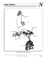
When the accelerator pedal is depressed, the accelera-
tor cable moves upwards, overcoming the resistance of
the accelerator return spring (Ref Fig. 1 on page N-1).
The rear of the accelerator cable is connected to the gov-
ernor lever. The other side of the governor lever is con-
nected to the governor cable. The other end of the
governor cable is attached to carburetor.
As the accelerator pedal is depressed, the accelerator
cable pulls the governor lever which rotates and pulls the
governor cable attached to the carburetor throttle lever.
When the accelerator cable pulls against the accelerator
cable/governor spring, the spring compresses until it
overcomes the resistance exerted by the governor mech-
anism and its extension spring. As the accelerator cable/
governor spring overcomes these forces, the governor
lever moves and the motion is transferred through the
governor cable to the throttle lever on the carburetor.
Governor Operation
To reduce the possibility
of serious personal inju-
ry or d e at h result ing
from a loss of control by the vehicle operating above
the factory specified speed, never tamper with the
governor. Tampering with the governor may void the
warranty.
If the governor requires service, the
service must be performed by an autho-
rized service branch or distributor.
Until the vehicle reaches its governed speed, the vehicle
will continue to accelerate in direct relation to the accel-
erator pedal position. When the governed speed is
reached, the ground speed governor contained within the
transmission operates against the accelerator cable/gov-
ernor spring. The accelerator cable remains in the fully
open position while the governor compresses the spring
as it rotates and moves the governor cable to retard the
carburetor throttle lever.
It is the force of the accelerator cable/governor compres-
sion spring in response to accelerator pedal and gover-
nor lever position which controls the position of the
carburetor throttle plate. The compression spring pro-
vides cushioning of sudden changes in throttle linkage
position to provide smooth power transmission.
General Cable Adjustment Procedure
If any accelerator/governor cable adjustment is
made, it is necessary to go back and perform
the governor/accelerator cable adjustment again. This must be
done because any adjustment made in the accelerator/gover-
nor cable will affect the governor performance.
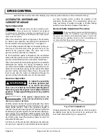
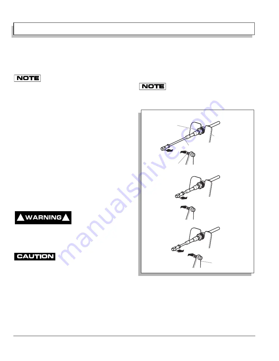
Properly adjusted, the cable should be short enough to
be slightly loose but not too short to be pulling on the
lever when at rest (Ref Fig. 2 on page N-2).
!
!
Fig. 2 Cable Adjustment
Too Long
Ball Joint
Adjustment Nuts
Mounting Bracket
Cable
Too Short
Correct
Lever
Summary of Contents for ST 4X4
Page 6: ...Page iv Repair and Service Manual TABLE OF CONTENTS Notes...
Page 10: ...Repair and Service Manual SAFETY INFORMATION Page viii Notes...
Page 12: ...GENERAL INFORMATION ROUTINE MAINTENANCE Page A ii Repair and Service Manual Notes...
Page 24: ...SAFETY Page B ii Repair and Service Manual Notes...
Page 34: ...BODY AND TRUCKBED Page C ii Repair and Service Manual Notes...
Page 50: ...BRAKES Page D ii Repair and Service Manual Notes...
Page 68: ...CONTINUOUSLY VARIABLE TRANSMISSION CVT Page E ii Repair and Service Manual Notes...
Page 74: ...DIRECTION AND DRIVE SELECTOR Page F ii Repair and Service Manual Notes...
Page 80: ...ELECTRICAL Page G ii Repair and Service Manual Notes...
Page 114: ...FRONT SUSPENSION AND STEERING Page J ii Repair and Service Manual Notes...
Page 128: ...FUEL SYSTEM Page K ii Repair and Service Manual Notes...
Page 136: ...PAINT Page L ii Repair and Service Manual Notes...
Page 142: ...REAR AXLE AND SUSPENSION Page M ii Repair and Service Manual Notes...
Page 152: ...SPEED CONTROL Page N ii Repair and Service Manual Notes...
Page 160: ...TROUBLESHOOTING Page P ii Repair and Service Manual Notes...
Page 168: ...WHEELS AND TIRES Page R ii Repair and Service Manual Notes...
Page 174: ...GENERAL SPECIFICATIONS Page S ii Repair and Service Manual Notes...
Page 180: ...LIMITED WARRANTY Page T ii Repair and Service Manual Notes...
Page 182: ...Page T 2 Repair and Service Manual LIMITED WARRANTY Notes...

