BRAKES
Page D-5
Repair and Service Manual
Read all of Section B and this section before attempting any procedure. Pay particular attention to all Notes, Cautions and Warnings
Teflon tape............................................................... A/R
The master cylinder is located under the cowl and is con-
nected to the brake pedal by clevis yoke.
It is important to maintain proper fluid levels in the master
cylinder. The fill caps for the cylinder are located under
the cowl. To prevent contamination when checking fluid,
wipe off any dirt from fill cap before removing it. Reser-
voir fluid level should be checked per ‘Periodic Service
Schedule’ Section in GENERAL INFORMATION AND
ROUTINE MAINTENANCE. When required, clean fresh
DOT 3 standard automotive brake fluid should be added
to maintain fluid level between the maximum and mini-
mum level indicators of the reservoirs.
Turn vehicle key to ‘OFF’ and remove. Insure all optional
electrical accessories are turned OFF. Remove the bat-
tery (Ref Battery Removal And Installation section in
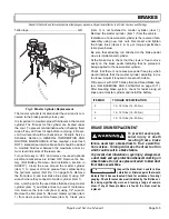
SAFETY). Clean the area around the master cylinder
(item 1) to prevent dirt and grease from contaminating
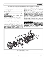
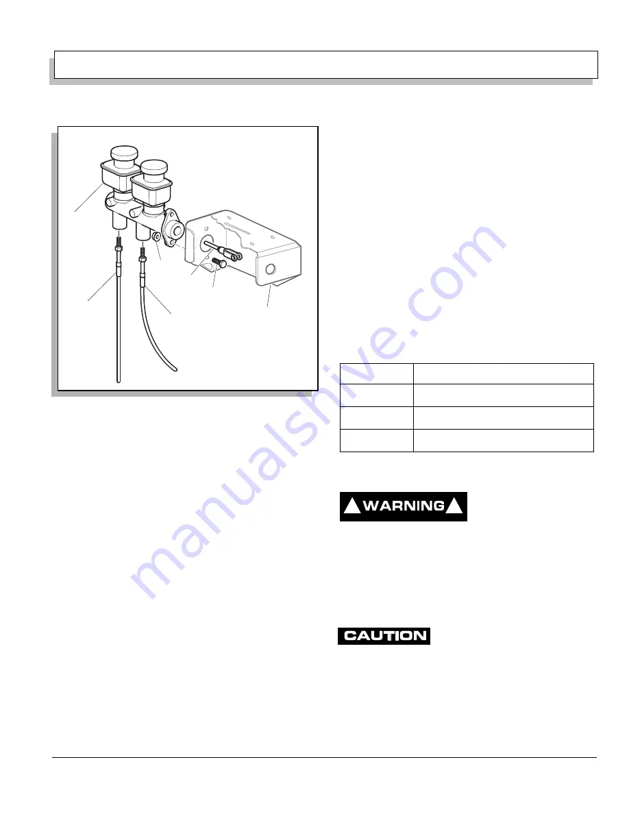
the hydraulic system (Ref Fig. 3 on page D-5). Remove
the front (item 2) and rear brake lines (item 3) using 3/8"
wrench where they connect to master cylinder (item 1).
Use a catch pan for the used brake fluid and plug master
cylinder (item 1) and brake lines to prevent contamina-
tion. Remove the lock nuts (item 4) using 1/2" wrench.
Remove the bolt (item 5). Remove master cylinder (item
1) from clevis yoke vehicle frame (item 6). Clevis yoke
(item 7) is not fastened to master cylinder (item 1).
Remove the master cylinder (item 1) from the vehicle.
Installation of a new master cylinder is the reverse of dis-
assembly using new lock nuts. Reconnect and tighten
the brake lines (items 2 & 3) per torque specification
table given below.
Be sure that actuating rod attached to the brake pedal
clevis is inside master cylinder.
At the brake clevis, check that the clevis is free to move
easily on the brake pedal indicating that no preload is
being applied to the new master cylinder.
Check that there is not excessive pedal free play which
would indicate that the master cylinder actuating rod is
too loose. Adjust if required to meet both criteria.
Fill reservoir with DOT 3 brake fluid and bleed brake sys-
tem (Ref BLEEDING AND FLUSHING on page D-11).
After bleeding brake system, check for leaks along all
lines and at master cylinder and install the battery.
BRAKE DRUM REPLACEMENT
To prevent severe per-
sona l injury or death
resulting from a brake
failure, never turn a brake drum to ‘true’ a worn fric-
tion surface. Turning will make the drum too thin
which could result in a brake failure.
To prevent dust inhalation or eye injury, always wear
a dust mask and eye protection whenever working on
wheel brakes. Do not use pressurized air to blow dust
from brake assemblies.
Inspect the brake drum. Look for a blue
coloration or blistered paint that would
indicate that it has overheated. Check for evidence of scoring/
gouging. Check for excessive wear indicated by the friction sur-
face being significantly worn and leaving a ledge of unworn
drum. If any of these problems are found, the drum must be
replaced.
Fig. 3 Master Cylinder Replacement
1
3
2
7
4
6
5
ITEM NO
TORQUE SPECIFICATION
2
10 - 15 ft. lbs (14 - 20 Nm)
3
10 - 15 ft. lbs (14 - 20 Nm)
4
12 - 15 ft. lbs (16 - 20 Nm)
!
!
Summary of Contents for ST 4X4
Page 6: ...Page iv Repair and Service Manual TABLE OF CONTENTS Notes...
Page 10: ...Repair and Service Manual SAFETY INFORMATION Page viii Notes...
Page 12: ...GENERAL INFORMATION ROUTINE MAINTENANCE Page A ii Repair and Service Manual Notes...
Page 24: ...SAFETY Page B ii Repair and Service Manual Notes...
Page 34: ...BODY AND TRUCKBED Page C ii Repair and Service Manual Notes...
Page 50: ...BRAKES Page D ii Repair and Service Manual Notes...
Page 68: ...CONTINUOUSLY VARIABLE TRANSMISSION CVT Page E ii Repair and Service Manual Notes...
Page 74: ...DIRECTION AND DRIVE SELECTOR Page F ii Repair and Service Manual Notes...
Page 80: ...ELECTRICAL Page G ii Repair and Service Manual Notes...
Page 114: ...FRONT SUSPENSION AND STEERING Page J ii Repair and Service Manual Notes...
Page 128: ...FUEL SYSTEM Page K ii Repair and Service Manual Notes...
Page 136: ...PAINT Page L ii Repair and Service Manual Notes...
Page 142: ...REAR AXLE AND SUSPENSION Page M ii Repair and Service Manual Notes...
Page 152: ...SPEED CONTROL Page N ii Repair and Service Manual Notes...
Page 160: ...TROUBLESHOOTING Page P ii Repair and Service Manual Notes...
Page 168: ...WHEELS AND TIRES Page R ii Repair and Service Manual Notes...
Page 174: ...GENERAL SPECIFICATIONS Page S ii Repair and Service Manual Notes...
Page 180: ...LIMITED WARRANTY Page T ii Repair and Service Manual Notes...
Page 182: ...Page T 2 Repair and Service Manual LIMITED WARRANTY Notes...

