BRAKES
Page D-9
Repair and Service Manual
Read all of Section B and this section before attempting any procedure. Pay particular attention to all Notes, Cautions and Warnings
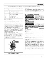
Tighten the hardware and brake lines per torque specifi-
cation table given below.
Replacing an Adjuster
Replace the adjuster assembly if the adjuster requires
more than 50 in. lbs (5.6 Nm) torque to rotate.
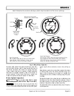
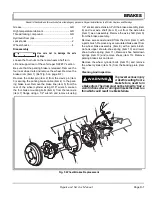
Secure the adjuster arm with locking pliers and remove
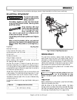
the torx bolt (item 1) on the back side of the backing plate
(item 2) with a torx driver (Ref Fig. 7 on page D-9). The
bolt may shear off which is acceptable. Remove and dis-
card all adjuster components. Clean the backing plate
surfaces that contact with the adjuster (item 3).
Prepare to install the new adjuster by applying a light
coat of grease to the belleville washer (item 4). Install the
washer (item 5) onto the adjuster arm with arch up as
shown in the figure below.
Apply thread locking compound to the bolt.
Insert the nose of the tube nut (item 6) into the backing
plate (item 2). Install the bolt (item 1) into the tube nut
(item 6) and tighten to 9 - 10 ft. lbs (12 - 14 Nm) torque.
It is recommended to replace both adjusters (item 3), if
one is found to require replacement.
Adjustment
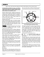
After the brake system has been bled, make 3 to 10 for-
ward and reverse stops by applying firm pressure to the
brake pedal on each stop to bring shoes to proper adjust-
ment.
FRONT DISC BRAKE REPLACEMENT
To prevent dust inhala-
tion or eye injury, always
wear a dust mask and
eye protection whenever working on wheel brakes.
Do not use pressurized air to blow dust from brake
assemblies.
Caliper Replacement
To prevent serious per-
sona l injury or death
resulting from a brake
failure resulting from contaminated brake fluid, never
reuse any excess fluid or return to the original con-
tainer. Dispose of brake fluid properly.
Tool List
Qty. Required
Floor jack, 1 1/2 ton..................................................... 1
Jack stands ................................................................. 2
Wheel chocks .............................................................. 4
Torque wrench, 1/2" drive, ft. lbs ................................. 1
Impact wrench, 1/2" drive
Extension, 6", 1/2" drive ............................................. 1
Socket, 3/4", 1/2" drive ................................................ 1
Impact socket, 3/4", 1/2" drive ..................................... 1
Allen wrench, 9 mm, 3/8" drive.................................... 1
Wrench, 3/8"................................................................ 1
Catch Pan.................................................................... 1
Park the vehicle on a level surface, engage park brake.
Loosen the four nuts on the front wheels half turn. Lift
and support front of the vehicle per SAFETY section.
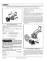
Remove the four front wheel nuts using 3/4" impact
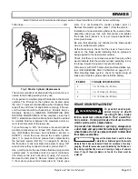
socket and remove the wheel. Remove the bolt (item 1)
using 3/4" socket and extension (Ref Fig. 8 on page D-
10). Remove the washer (item 2). Remove the front
brake line (item 3) using 3/8" wrench and drain fluid into
catch pan for proper disposal. Remove the caliper (item
4).
ITEM NO
TORQUE SPECIFICATION
6
28 - 31 ft. lbs ( 38 - 42 Nm)
5
10 - 15 ft. lbs (14 - 20 Nm)
15
10 ft. lbs (14 Nm)
19
9 - 10 ft. lbs (12 - 14 Nm)
Fig. 7 Replacing an Adjuster
4
3
6
2
1
5
!
!
!
!
Summary of Contents for ST 4X4
Page 6: ...Page iv Repair and Service Manual TABLE OF CONTENTS Notes...
Page 10: ...Repair and Service Manual SAFETY INFORMATION Page viii Notes...
Page 12: ...GENERAL INFORMATION ROUTINE MAINTENANCE Page A ii Repair and Service Manual Notes...
Page 24: ...SAFETY Page B ii Repair and Service Manual Notes...
Page 34: ...BODY AND TRUCKBED Page C ii Repair and Service Manual Notes...
Page 50: ...BRAKES Page D ii Repair and Service Manual Notes...
Page 68: ...CONTINUOUSLY VARIABLE TRANSMISSION CVT Page E ii Repair and Service Manual Notes...
Page 74: ...DIRECTION AND DRIVE SELECTOR Page F ii Repair and Service Manual Notes...
Page 80: ...ELECTRICAL Page G ii Repair and Service Manual Notes...
Page 114: ...FRONT SUSPENSION AND STEERING Page J ii Repair and Service Manual Notes...
Page 128: ...FUEL SYSTEM Page K ii Repair and Service Manual Notes...
Page 136: ...PAINT Page L ii Repair and Service Manual Notes...
Page 142: ...REAR AXLE AND SUSPENSION Page M ii Repair and Service Manual Notes...
Page 152: ...SPEED CONTROL Page N ii Repair and Service Manual Notes...
Page 160: ...TROUBLESHOOTING Page P ii Repair and Service Manual Notes...
Page 168: ...WHEELS AND TIRES Page R ii Repair and Service Manual Notes...
Page 174: ...GENERAL SPECIFICATIONS Page S ii Repair and Service Manual Notes...
Page 180: ...LIMITED WARRANTY Page T ii Repair and Service Manual Notes...
Page 182: ...Page T 2 Repair and Service Manual LIMITED WARRANTY Notes...

