BRAKES
Page D-10
Repair and Service Manual
Read all of Section B and this section before attempting any procedure. Pay particular attention to all Notes, Cautions and Warnings
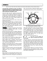
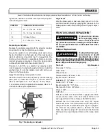
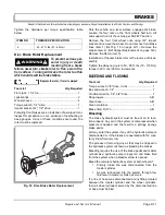
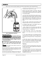
Installation of the brake caliper is the reverse of disas-
sembly. Connect and tighten the brake line per torque
specification table.
Tighten the hardware per torque specification table
below.
Bleed the brakes after installation.
Disc Brake Pad Replacement
To prevent severe per-
sonal injury or death
r e s u l t i n g f r o m w o r n
brake pads or loose components, always replace the
brake pads on both wheels and in pairs. Be sure to
replace C-clips with new ones.
Replace both brake pads on wheel, if
one or more brake pads are worn below
.1
"
(2.5mm) thickness at any point.
Do not allow caliper to hang from brake line. If caliper is
removed, it should be supported by wire ties.
Tool List
Qty. Required
Floor jack, 1 1/2 ton..................................................... 1
Jack stands ................................................................. 2
Wheel chocks .............................................................. 4
Torque wrench, 1/2" drive, 165 ft. lbs capacity ............ 1
Impact socket, 3/4", 1/2" drive ..................................... 1
Allen wrench, 9 mm, 3/8" drive ....................................1
Needle nose pliers .......................................................1
Park the vehicle on a level surface, engage park brake.
Loosen the four nuts on the front wheels half turn. Lift
and support front of the vehicle per SAFETY section.
Remove the four front wheel nuts using 3/4" impact
socket and remove the wheel. Do not remove front brake
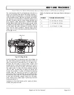
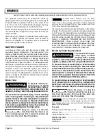
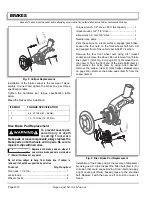
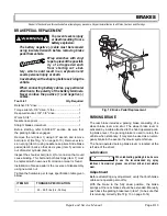
lines (item 1) (Ref Fig. 9 on page D-10). Remove the C-
clip (item 3) from the front end of the slide bolts (item 4)
and remove the bolts (item 4) using Allen wrench.
Remove the caliper (item 2) (Ref Caliper Replacement
on page D-9). Remove the brake pads (item 5) from the
caliper (item 2).
Installation of the brake pads is the reverse of disassem-
bly using new C-clips. Inspect the Allen bolt (item 4) for
corrosion that could cause binding. Clean bolt and apply
a light coating of lithium based grease to the shoulder
bolt. Replace it with the new one if corrosion or wear is
found.
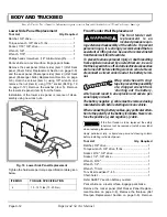
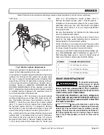
Fig. 8 Caliper Replacement
ITEM NO
TORQUE SPECIFICATION
1
42 - 47 ft.lbs (57 - 64 Nm)
3
10 - 15 ft. lbs (14 - 20 Nm)
4
2
1
3
!
!
Fig. 9 Disc Brake Pad Replacement
5
2
3
4
1
Summary of Contents for ST 4X4
Page 6: ...Page iv Repair and Service Manual TABLE OF CONTENTS Notes...
Page 10: ...Repair and Service Manual SAFETY INFORMATION Page viii Notes...
Page 12: ...GENERAL INFORMATION ROUTINE MAINTENANCE Page A ii Repair and Service Manual Notes...
Page 24: ...SAFETY Page B ii Repair and Service Manual Notes...
Page 34: ...BODY AND TRUCKBED Page C ii Repair and Service Manual Notes...
Page 50: ...BRAKES Page D ii Repair and Service Manual Notes...
Page 68: ...CONTINUOUSLY VARIABLE TRANSMISSION CVT Page E ii Repair and Service Manual Notes...
Page 74: ...DIRECTION AND DRIVE SELECTOR Page F ii Repair and Service Manual Notes...
Page 80: ...ELECTRICAL Page G ii Repair and Service Manual Notes...
Page 114: ...FRONT SUSPENSION AND STEERING Page J ii Repair and Service Manual Notes...
Page 128: ...FUEL SYSTEM Page K ii Repair and Service Manual Notes...
Page 136: ...PAINT Page L ii Repair and Service Manual Notes...
Page 142: ...REAR AXLE AND SUSPENSION Page M ii Repair and Service Manual Notes...
Page 152: ...SPEED CONTROL Page N ii Repair and Service Manual Notes...
Page 160: ...TROUBLESHOOTING Page P ii Repair and Service Manual Notes...
Page 168: ...WHEELS AND TIRES Page R ii Repair and Service Manual Notes...
Page 174: ...GENERAL SPECIFICATIONS Page S ii Repair and Service Manual Notes...
Page 180: ...LIMITED WARRANTY Page T ii Repair and Service Manual Notes...
Page 182: ...Page T 2 Repair and Service Manual LIMITED WARRANTY Notes...

