background image

1. 

Check wear of hanger assembly bushing

 by moving hanger assembly up and down.  

    If hanger assembly moves up and down and the thickness of 2 quarters can be inserted  
    between hanger assembly and load cell the hanger assembly needs to be replaced. 
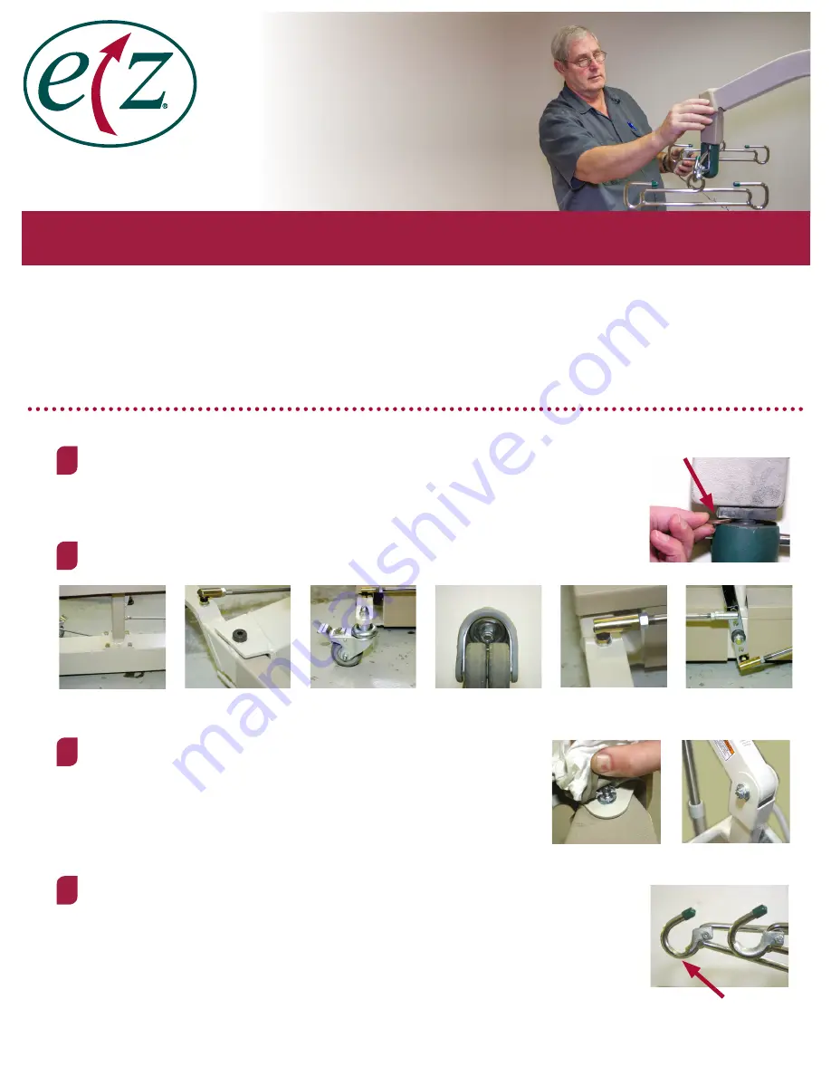
2. 

Check all bolts

 to ensure they are tight.

3. 

Check boom to hanger assembly pivot bolt

, peel rubber back to  

    assure nut is tight and cotter pin is in place. Check boom to mast pivot     


    bolt by removing plastic cap to assure nut is tight and cotter pin is in  
    place. If plastic cap is missing order replacement.


4.

 Check the point where sling hanger and hanger spreader bar meet

. If excessively  

    worn, replace the bushings immediately. The hanger spreader and sling hanger wear  
    points need to be checked for wear. If hooks appear worn, call EZ Way for instructions.


BASE                          PIVOT                    REAR WHEEL            FRONTWHEEL               LINKAGE                  SPREADER            

BADLY WORN

NEEDS REPLACEMENT

BOOM TO MAST

BOOM TO HANGER

EZ Way Smart Lift

®


Safety

 & 

Maintenance Checklist

EZ Way, Inc.

“Your Total Patient  

Lift Solution”

The EZ Way Smart Lift

®

 requires a minimum of servicing to keep it in good working order.  Nevertheless, it is important that 

certain basic checks be periodically made by maintenance staff to ensure on-going safety throughout the life of the device.

The manufacturer suggests that the following components and operating points be scheduled for inspection at intervals not 
greater than six months.  Any detected deficiency must be rectified before the lift is put back into service.

1

2

3

4

Summary of Contents for Smart Lift L500

Page 1: ...Service Manual Model L500 and L600 Smart Lift Form 1 144 Rev 2 5 19 WARNING Cancer and Reproductive Harm www P65Warnings ca gov...

Page 2: ...Fax 712 542 1899 www ezlifts com Table of Contents Parts Breakdown 3 Monthly Maintenance Checklist 5 Smart Lift Operating Instructions 7 Scale Calibration 8 Advanced Smart Lift Features 9 Wiring Sche...

Page 3: ...EZ Way Inc EZ Way Inc 800 627 8940 Fax 712 542 1899 www ezlifts com 3 L500 L600 Parts Diagram...

Page 4: ...ader Bushing Kit 17 12014 Actuator Assembly Lift 18 12706 Hand Control Assembly 19 12146 Bed Guard 20 12788 Base Assembly Lift 500 lb Std Casters 600 EZ Smart Lift Model L600 Item Part No Description...

Page 5: ...ce the bushings immediately The hanger spreader and sling hanger wear points need to be checked for wear If hooks appear worn call EZ Way for instructions BASE PIVOT REAR WHEEL FRONTWHEEL LINKAGE SPRE...

Page 6: ...ing properly Hair that gets picked up and wrapped in between wheels should be cleaned out so that the lift will roll easily Do a visual check for any damaged missing or loose parts Repair as necessary...

Page 7: ...bol indicating that the weight is recalled MENUS Navigating through menus 1 Pressing the Up or Down keys will move also described as scrolling below through menu items 2 Pressing the Right Toggle Swit...

Page 8: ...sure the scale is functional 5 Enter the calibration menu After power up sequence press and hold the DOWN key followed quickly by the UP key and hold both keys for 5 seconds 6 Press the UP key to cali...

Page 9: ...tomer will need to wait 15 minutes to cool the actuator motor Actuator Overload For Arm Protection 1 When an Up or Down command is executed the circuit board monitors current consumed by the actuator...

Page 10: ...e since the last inspection exceeds 30 days a reminder message will appear when the unit is powered up The purpose of the inspection reminder is to notify the customer that the lift or stand needs to...

Page 11: ...is read only information provides customer feedback for accidental lifting of a trapped sling accidental lifting of arm against obstruction or accidental lifting of overweight patient Lift Stand Total...

Page 12: ...EZ Way Inc EZ Way Inc 800 627 8940 Fax 712 542 1899 www ezlifts com 12 Smart Lift Wiring Schematic...

Page 13: ...ke sure on off button is not flattened out Check if green LED is flashing on board Flashing LED indicates the PCB is getting power Make sure W6 jumper is in place No up down but display works Check co...

Reviews: