background image


3)


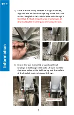
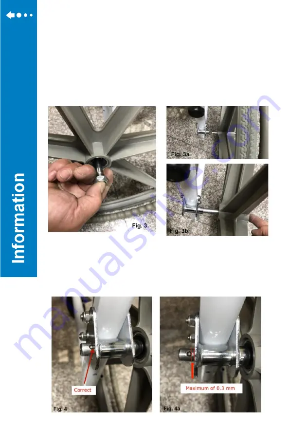
Once the axle is fully inserted through the wheel, 
align the axle end with the opening in the axle tube 
on the triangle bracket and slide the axle through it. 

Note that the lock release button must always be 
depressed while inserting and removing the axle. 


4)


Ensure the axle is inserted properly with ball 
bearings fully through the bracket. Please note the 
clearance between the ball bearing and the surface 
of the bracket must not exceed 0.3 mm.


Summary of Contents for 180-24

Page 1: ...EZee Life Products 34 Futurity Gate Unit 15 Concord Ontario L4K 1S6 22 24 Quick Release Wheels Assembly Instructions ...

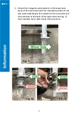
Page 2: ...le brackets to the lower back posts of the commode with the extended portion of the axle tube extending to the outside of the commode and the axle tube to the back of the back tube see Fig 1 Tools needed 4mm allen key 10mm wrench ...

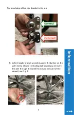
Page 3: ...e of triangle bracket is the top 2 After triangle bracket assembly press the button on the axle end to release the locking ball bearings and insert the axle through the wheel from hand rim side of the wheel see Fig 2 ...

Page 4: ... bracket and slide the axle through it Note that the lock release button must always be depressed while inserting and removing the axle 4 Ensure the axle is inserted properly with ball bearings fully through the bracket Please note the clearance between the ball bearing and the surface of the bracket must not exceed 0 3 mm ...

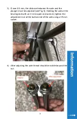
Page 5: ...nd the plunger must be adjusted see Fig 5 Holding the axle at the bearing end with an 11 mm open end wrench tighten the adjustment nut at the button end of the axle using a 19 mm socket 6 After adjusting the axle thread should be visible beyond the nut ...

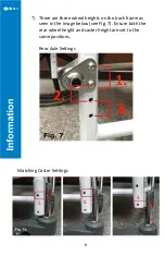
Page 6: ...ere are three wheel heights on the back frame as seen in the image below see Fig 7 Ensure both the rear wheel height and caster height are set to the same positions Rear Axle Settings Matching Caster Settings ...

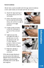
Page 7: ...ntil it is just snuggly attached 3 Position while assembly so that the locking bar is in front of the commode tire 4 Tighten clamp fully and apply the brake It should press in to the tire between 1 8 and when adjusted properly Check to ensure the wheel won t spin when the brake is applied 5 Repeat for wheel on opposite side of the commode If the wheels begin slipping at any time when the brakes ar...

Page 8: ...nt The warranty does not extend to consequential costs resulting from the fault or defect in the product in particular freight and travel costs loss of earnings expenses or other expenses which may occur The warranty does not cover normal wear and tear resulting from normal use or damage caused by accident misuse negligence or improper installation or assembly The vendor manufacturer will not acce...

Reviews: