background image

- 29 -

Miscellaneous

- 28 -

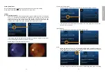
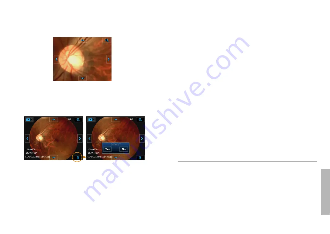
After the image is enlarged (1:1), the arrows would work as pan functions. Tap Zoom icon 

again to return the original scale.

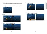
Deleting pictures

Tap the delete icon to delete the image. By using the “delete” functions on your camera, this 

only changes the file management information and does not completely delete the data from 

the memory card. When disposing of or transferring your memory cards, we recommend 

physically destroying them or using commercially available computer data erasing software to 

completely delete the data from the card. 

Move the 

enlarged section 

toward left

Move the 

enlarged section 

toward right

Move the enlarged 

section downward

Move the enlarged 

section upward

Miscellaneous

Files transferring

Transfer images to an electronic device (e.g., personal computer, laptop, or mobile phone) via 

the USB cable or SD card.

Viewing on a computer/laptop screen

Turn on UVC mode (

→ 15

) to simultaneously view images both on LCD panel and the com

-

puter/laptop screen.

Viewing on a TV screen

Connect the camera and a TV through a AV cable, you can simultaneously view images on 

both sides. 

Usage cautions and notes

When in use

• The camera may become warm if used for long periods of time, but this is not its fault.

• Keep the camera as far away as possible from electromagnetic equipment (such as micro

-

wave ovens, TVs, video games, etc.).

• Do not use the camera near radio transmitters or high-voltage lines.

• Never leave the camera and the battery in a car or on a car hood in the summer. Doing so 

may cause leakage of the battery electrolyte, overheating, fire, or a battery explosion due 

to the high temperature.

• If the optical lens and control unit get wet, do not attempt to dry with a heater, microwave, 

autoclave, or UV light.

• Do not extend the supplied cables. Do not keep the power cord near any heat source.

• When the camera is not in use, please disconnect the power plug and keep it in a safe 

place.

Summary of Contents for Horus+ Scope

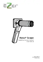
Page 1: ...Horus Scope Digital Eye Fundus Camera User Manual DOC No 2014 01 A Copyright 2014 MiiS Inc All right reserved ...

Page 2: ...ence of operations 21 Photo mode 22 Video mode 23 Fixation setting and holding position 24 Q A troubleshooting 26 Playback Display mode 27 Enlarged viewing 27 Deleting pictures 28 Miscellaneous Files transferring 29 Viewing on a computer laptop screen 29 Viewing on a TV screen 29 Usage cautions and notes 29 Technical description 33 Liability 34 Disposition 34 Symbols and standards 34 ...

Page 3: ...oreign material entering the camera through the lens or gaps around buttons Be especially careful because these conditions may dam age the camera and such damage may not be repairable In extremely dusty or sandy places Exposing the camera to rain or moisture Condensation when the lens or the monitor is fogged up Condensation may occur when the camera is exposed to sudden changes of temperature or ...

Page 4: ...xperience pain or be injured No compensation for missed shots We cannot compensate for missed shots if technical problems with the camera or card pre vent recording Also refer to Usage cautions and notes Please also refer to Usage cautions and notes 29 for more instructions of the battery SD card etc Please note that the actual controls and components menu items and other information of your camer...

Page 5: ... previewing photos Power indicator Brightness decrease increase in photo mode 0B 15B Bottom view AV out foot switch Mini USB Strap hook Optical Lens of Horus Scope EZ Horus 45 Digital Eye Fundus Camera Lens connect ring Contact surface Lens assembling mark Signal pad Rear view Lens assembling mark Cover glass and sensor Lens connect ring Lens connecting pins Battery cover SD slot ...

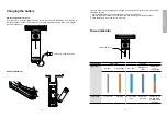
Page 6: ...ttom of battery cover with a finger or something pointed Tilt the battery cover and remove the battery cover by lifting it up Remove the original battery and replace a new battery along the correct direction Place the battery cover and secure it in place Power indicator System status Power off Power on Light color No light Orange light Blue light Blinking blue light Mixed blue and orange light Inf...

Page 7: ...wer indicator 11 will also turn on Step 4 To unlock the optical lens press the lens lock and then rotate the optical lens in a counterclockwise direction Then the optical lens will be unfastened Using the Setup mode Turn on the power To turn on the system press the power button 7 to turn on the control unit Approxi mately one to two seconds later the boot screen will appear on the LCD panel Once t...

Page 8: ...tured in full color If the setting is White LED White LED then the user observes images in full color and capture static images and motion pictures in full color Sample images of monochrome and full color Picture Color Temperature The picture color temperature has three levels the default setting is medium Low sets the color temperature for a warmer color tone High sets the color tem perature for ...

Page 9: ...e the mode is on the LCD panel will be turned off if the system is idle for three minutes Tap on the item to toggle the setting Date Setting User can change the current date setting from the screen Time Setting User can change the current time setting from the screen Format SD Card User can format the SD card NOTE All information will be deleted after SD card is formatted Factory Setting User can ...

Page 10: ... jpg E L ABCD12345 1 6 1 4 3 1 jpg No ID ID ABCD12345 Eye Left Hour Minute Second Patient ID Eye Left Hour Minute Second The image name is explained as follows EL Left eye photo taken by the eye fundus camera hour 16 minute 14 and sec ond 31 If the given patient number is ABCD12345 the image name would be written as ELABCD12345161431 jpg Create a new patient ID from scratch By gently pressing the ...

Page 11: ...or the video mode icon to enter a shooting mode Step 4 Mark left right eye By doing so the user can tell whether a photo video is left eye or right eye record from its file name Default value is left eye Step 5 Aim and preview Position the camera correctly and adjust to appropriate settings to get a clear preview 24 The image brightness can only be changed in photo mode whereas the fixation lamp c...

Page 12: ...s adjustment keys User interface 8 of the control unit to change value The higher value you set the brighter image you get Image brightness adjustment range Model Name Default Value Min Value Max Value Eye fundus camera EZ Horus 45 10 0 15 Reference Table Brightness Indicator Classification Note 0 5B Light Skin Blond 5 10B Light Skin Brunette 10B is default 10 15B Dark Skin Press fully Press halfw...

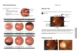
Page 13: ... lens at the same height of the eye being examined To stabilize the lens rest the lens on the part of the hand between the thumb and index finger and put your middle and index fingers on the examinee s forehead as showed in the following image The brightness of fixation LED Adjust by using the brightness adjust ment keys 5B is the maximum brightness level in fixation setting View the examined eye ...

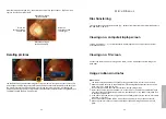
Page 14: ...e or white shadow on the bottom of image The lens is much higher than the visual axis Eyelashes are in the light path Cornea reflection Macula Vessels Optic disc Playback Display mode Touch the photo icon and then the display icon to see the photos that have been taken Display mode Click the left or right arrow symbols to go to the previous or next photo respectively Click the up or down arrow sym...

Page 15: ...Viewing on a computer laptop screen Turn on UVC mode 15 to simultaneously view images both on LCD panel and the com puter laptop screen Viewing on a TV screen Connect the camera and a TV through a AV cable you can simultaneously view images on both sides Usage cautions and notes When in use The camera may become warm if used for long periods of time but this is not its fault Keep the camera as far...

Page 16: ...C electromagnetic compatibility During installation and operation of the device observe the following instructions Do not use the device simultaneously with other electronic equipment to avoid electromag netic interference with the operation of the device Do not use or stack the device near on or under other electronic equipment to avoid elec tromagnetic interference with the operation of the devi...

Page 17: ...echnical Commission sets the essential requirements for electrical and electronic equipment that may disturb or be disturbed by other equipment The device complies with these requirements as shown in the tables in Symbols and standards EMC 34 Follow the guidance in the tables for use of the device in an electromagnetic environment Technical description Horus Scope EZ Horus 45 digital eye fundus ca...

Page 18: ...uirements applica ble to all ophthalmic instruments ISO 15004 1 2006 Equipment connected to the analog or digital interfaces must be certified according to the representative appropriate national standards such as EN 60601 1 and IEC 60601 1 Furthermore all configurations shall comply with the system standard IEC 60601 1 Anyone who connects additional equipment to the signal input part or signal ou...

Page 19: ...Hz d 1 2 80 MHz to 800 MHz d 2 3 800 MHz to 2 5 GHz where P is the maximum output power rating of the transmitter in watts W according to the transmitter manufacturer and d is the recom mended separation distance in meters m Field strengths from fixed RF transmitters as deter mined by an electromagnetic site survey a should be less than the compliance level in each frequency range b Interference m...

Reviews: