Page E-5
Repair and Service Manual
B
B
FRONT SUSPENSION AND STEERING
Read all of Section B and this section before attempting any procedure. Pay particular attention to Notices, Cautions, Warnings and Dangers.
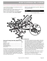
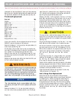
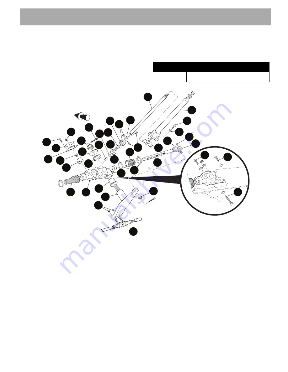
nuts (10) from the coupling (11) and remove shaft (12)
from the steering assembly.
Replace steering shaft in reverse order of removal. Gas-
ket (8) should be replaced with a new gasket.
Bolts (9) should be tightened to a light drag between
shaft (12) and coupling (11).
Do not over tighten
.
Bolts (6) must be replaced with new bolts. Tighten bolts
to the specified torque.
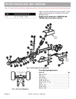
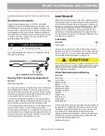
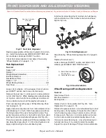
Fig. 7 Steering Components
Steering Housing Assembly Replacement
Tool List
Qty.
Needle nose pliers....................................................... 1
Wrench, 11/16" ............................................................ 1
Ball joint separator....................................................... 1
Plastic faced hammer.................................................. 1
Wrench, 5/8"................................................................ 2
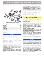
Except for major damage to the steering assembly hous-
ing, there is no need to remove the housing (13) from
the vehicle. The only components requiring replacement
due to wear that would require removing the housing
from the vehicle would be the replacement of the bear-
ing (14) and bushing (15). (Ref Fig. 7) The bearing and
bushing must be pressed out.
To remove the steering housing assembly, remove the
driver side front wheel, remove the steering wheel (3),
and remove the steering shaft (12) as instructed
above.Loosen the two nuts (16) until ball joint (17) end
threads are protected. Using a ball joint separator as a
lever, apply pressure to ball joint and tap nut with plastic
faced hammer to release ball joint from idler arm (18).
Remove tie rods, and lastly, remove the two epoxy patch
bolts (19) and longer bolt (44) attaching the steering
housing to the frame mount and remove the housing
from the underside of the vehicle.
Replace steering housing in reverse order of removal.
Bolts (19) must be replaced with new bolts. Tighten
mounting bolts to the specified torque.
Tighten tie rod nuts (16) to the specified torque.
ITEM
TORQUE SPECIFICATION
6
18 - 22 ft. lbs (25 -30 Nm)
Front of Vehicle
14
16
28
13
15
8
17
20
42
30
27
35
9
8
36
43
7
6
5
12
11
10
38
37
39
40
25
29
22
41
23
24
31
32
33
34
26
21
19
19
44
Summary of Contents for EXPRESS L4
Page 6: ...Page iv Repair and Service Manual NOTES TABLE OF CONTENTS ...
Page 207: ......

