Page F-10
Repair and Service Manual
B
ELECTRONIC SPEED CONTROL
Read all of Section B and this section before attempting any procedure. Pay particular attention to Notices, Cautions, Warnings and Dangers.
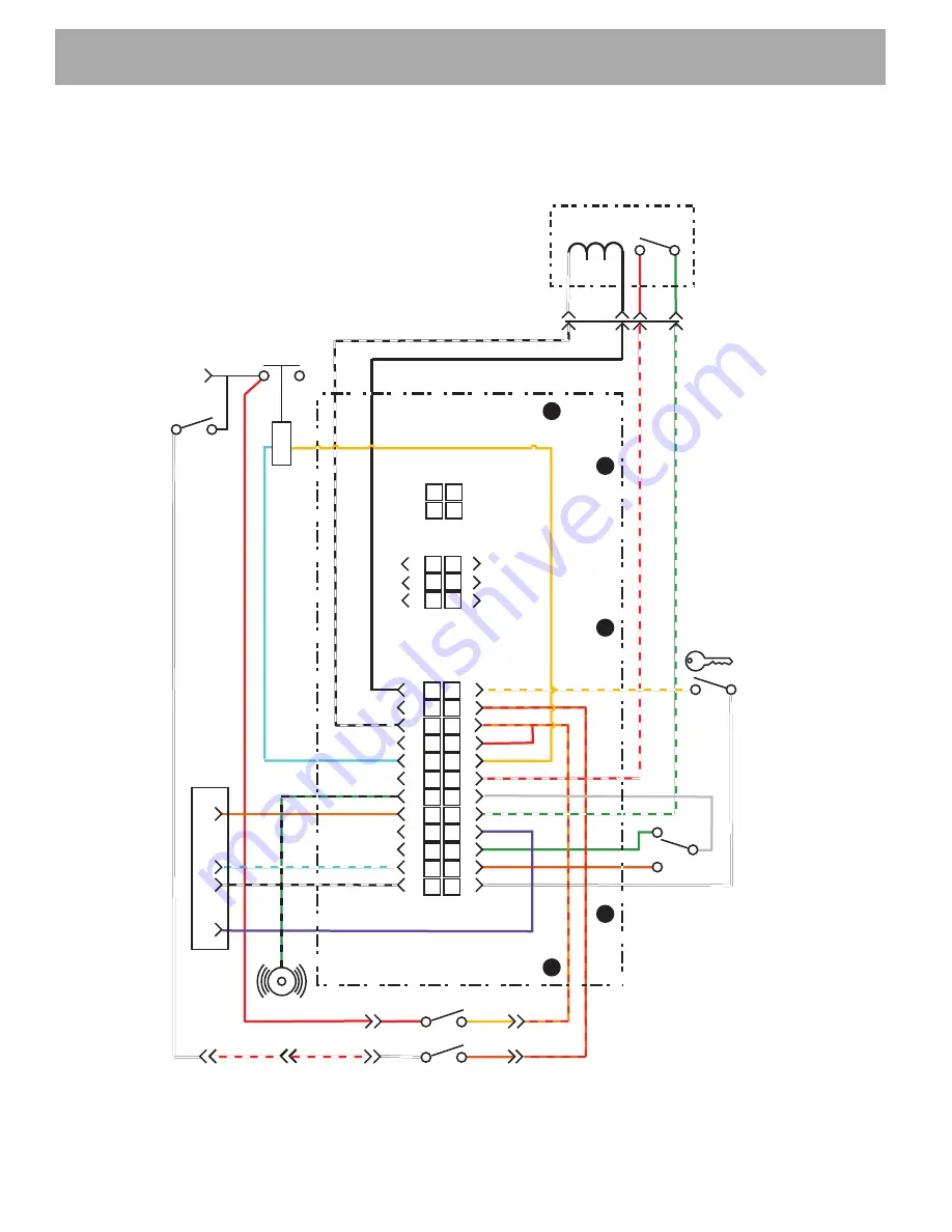
Fig. 11 J-1 Pin Connector Diagnostics
+
+
-
B
B
F2
M-
Charging
Connector
Pedal Box
ITS
MS3
GRN
RED
BLK
BLK
WHT
RED
RED
RED
RED
WHT/YEL
YEL
Solenoid
Reed
Switch
ORN/RED
RED/YEL
YEL
RED/WHT
RED/WHT
RED/WHT
GRY
GRN/WHT
GRN
VIO
ORN
WHT
FWD
REV
N
Direction
Selector
Switch
Key
Switch
WHT
WHT
WHT
F1
YEL
Tow Switch
ORN
ORN/RED
Aux
BLK
SPARE
SPARE
SPARE
SPARE
SPARE
WHT/BLK
BLU
GRN/BLK
BRN
BLU/WHT
BLK/WHT
Reverse
Buzzer
Performance
Plug
1
5
3
2
J3
J2
1
2
3
1
2
3
4
5
6
4
5
6
7
8
9
10
11
12
13
14
15
16
17
18
19
20
21
22
23
24
J1
Summary of Contents for EXPRESS L6 2012
Page 6: ...Page iv Repair and Service Manual NOTES TABLE OF CONTENTS...
Page 201: ......


