Page K-2
ELECTRICAL COMPONENTS & WIRING
Repair and Service Manual
Read all of Section B and this section before attempting any procedure. Pay particular attention to all Notes, Cautions and Warnings.
B
instrument panel through a slot in the cowl, squeeze
the legs of the tab together and push to the back of the
vehicle while pulling forward on the cowl. Repeat for
the other side —
at this point the cowl is completely
loose
— remove the cowl.
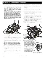
4. Loosen the trim panel (12) by pulling it away from the
instrument panel along the upper edge then grip the
ball holder with both hands and pull away from the
instrument panel (13); move to the other side of the
vehicle and grip the ball holder on that side with both
hands and pull it away from the instrument panel (13).
5. Disconnect wires to the instruments located in the trim
panel then remove the trim panel.
Fig. 2 Instrument Panel & Trim
6. Remove the wiring harness from the front splash
shield retaining clips.
7. If vehicle is equipped with brake lights, disconnect the
two wires to the brake light relay located on the front
splash shield tab extending into the cup holder.
8. Remove the Diagnostic Plug from the bottom of the
cup holder.
9. Disconnect the plug to the throttle enable switch.
10. Disconnect the plug from the rotary position sensor.
11. Disconnect the plug from the brake enable switch.
12. Disconnect the wires from the rotary position sensor.
13. Remove the two Torx head screws that secure the
front edge of the rear body and seat support frame to
the floorboard.
14. Remove the two Torx head screws along back edge of
the seat opening that secure the rear body to the seat
support.
15. Remove the four Torx head screws; two on each side
that secure the lower edge of the rear body to the
floorboard.
16. Remove the two Torx head screws from the bagwell
that secure the rear body to the rear bumper.
17. Remove two Torx head screws securing the controller
splash shield to the rear body and the christmas tree
rivet securing it to the controller heat sink, raise splash
shield and move it out of the way.
18. Raise the front edge of the rear body several inches
and support it with a block or piece of 2" x 4" wood.
This will allow the harness to be passed between the
rear body and the floorboard.
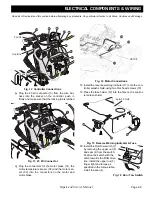
19. Unplug the large 23 pin connector (3) from the control-
ler by lifting up on the locking tab and pulling the con-
nector housing away from the controller.
20. Disconnect the plug for the resistor as well as the plug
to the sensor on top of the resistor
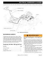
Fig. 3 Controller
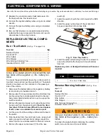
21. Remove the Run/Tow switch
from the splash shield by remov-
ing the seal (4) and upper nut (5)
then push the switch (7) through
the splash shield. CE vehicles
will have a key switch in place of
the toggle switch, unscrew the
top ring to release the switch
from the splash shield.
Check
the Run / Tow label, if it has
become difficult to read
replace it with a new one avail-
able from service parts.
Fig. 4 Run / Tow Switch
Controller
Red Wire to
Battery BL+
Red Wire from
Solenoid to
Controller B+
Heatsink
Resistor
Solenoid
Sensor


