Page K-4
ELECTRICAL COMPONENTS & WIRING
Repair and Service Manual
Read all of Section B and this section before attempting any procedure. Pay particular attention to all Notes, Cautions and Warnings.
B
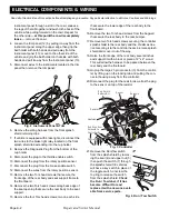
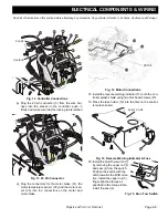
e) Connect the wires to the brake pedal rotary posi-
tion sensor (8) and the brake enable switch con-
nector (9).
f) Place pedal assembly in position on the floorboard
and secure with four socket head hex screws (10).
g) Route the remaining wires in the floorboard chan-
nel that runs up under the instrument panel.
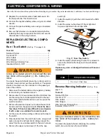
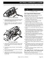
h) Feed the connectors for the key switch, the
optional fuel gauge/state of charge meter and the
diagnostic plug through the opening in the cup
holder base (12). Place the diagnostic plug (13)
into the cup holder base and route the connectors
for the key switch (14) and the fuel gauge/state of
charge meter over the front splash shield.
Fig. 9 Cup Holder
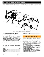
i) Route the wires (14) for the key switch and the
optional fuel gauge/state of charge meter through
the guide (15) on the front splash shield and the
connectors for the key switch and the optional fuel
gauge/state of charge meter through the opening
(16) in the back of the instrument pane
l.
Fig. 10 Front Splash Shield
j) Connect the wire harness to the key switch.
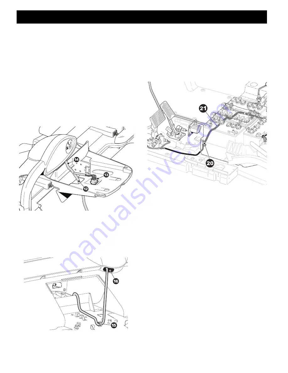
k) Route the two rear sections of the harness
between the rear body and the battery pack mak-
ing sure that the longer wires (21) are routed to the
passenger side.
l) Plug the connector (20) for the charger receptacle
into the connector on the main wiring harness.
Fig. 11 Charger Receptacle
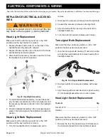
m) Install the Red wire (23) to the B+ terminal of the
controller.
(Do not over tighten the terminal
screw (24).)
n) Install the solenoid (25) on the controller heat sink
using two hex head bolts (26). Make sure that the
black wires from the solenoid to the wire harness
are located at the top of the solenoid.
o) Connect the Red wire (23) from the controller B+ to
the bottom terminal of the solenoid (25), using a
slim wrench to keep the back up nut from moving
when tightening the top nut (27). Connect the Red
wire (29) from the battery and the yellow wire (28)
from the wiring harness to the top terminal on the
solenoid, using a slim wrench to keep the back up
nut from moving when tightening the top nut (27).
Do not over tighten the nut


