ELECTRICAL COMPONENTS & WIRING
Page K-5
Repair and Service Manual
Read all of Section B and this section before attempting any procedure. Pay particular attention to all Notes, Cautions and Warnings.
B
B
.
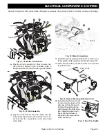
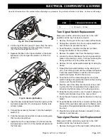
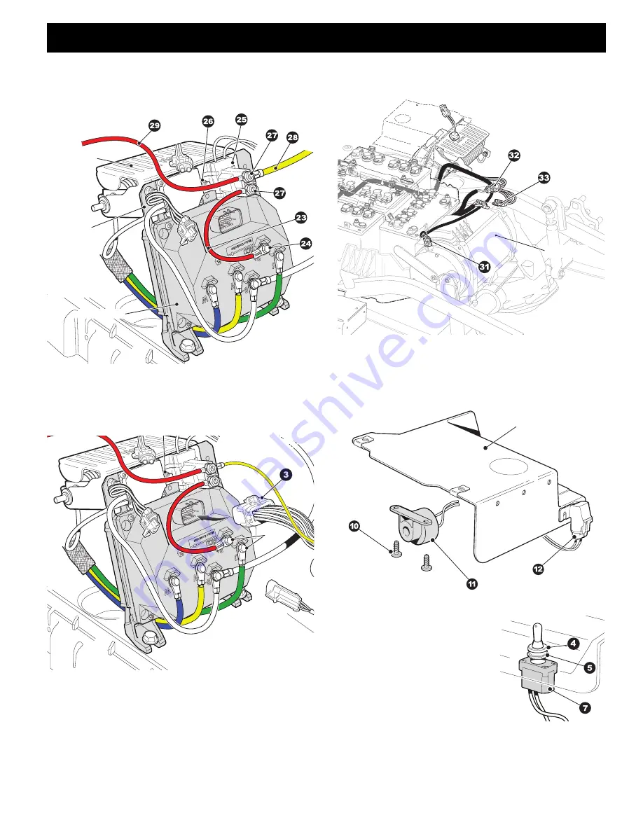
Fig. 12 Controller Connections
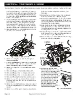
p) Plug the 23 pin connector (3) from the wire har-
ness into the socket on the controller, push in
firmly and make sure that the locking tab is latched
.
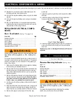
Fig. 13 23 Pin Connector
q) Plug the connectors for the motor brake (31), the
motor temperature sensor (32) and the motor sen-
sor (33) into the connectors on the motor and
motor brake
.
Fig. 14 Motor Connections
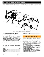
18. Install the reverse warning indicator (11) onto the con-
troller splash shield using two Torx head screws (10)
19. Press the fuse holder (12) into the hole on the control-
ler splash shield.
Fig. 15 Reverse Warning Indicator & Fuse
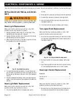
20. Install the Run/Tow switch (7)
by removing the upper nut (5)
and seal (4) from the switch.
Position the switch with the
notch towards the RUN direc-
tion. Install the upper nut (5)
finger tight and torque as
specified in the torque table,
install the seal (4).
Fig. 16 Run / Tow Switch
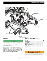
Controller
Heatsink
Resistor
MOTOR
Splash Shield

