ELECTRICAL COMPONENTS & WIRING
Page K-13
Repair and Service Manual
Read all of Section B and this section before attempting any procedure. Pay particular attention to all Notes, Cautions and Warnings.
B
B
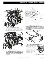
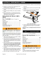
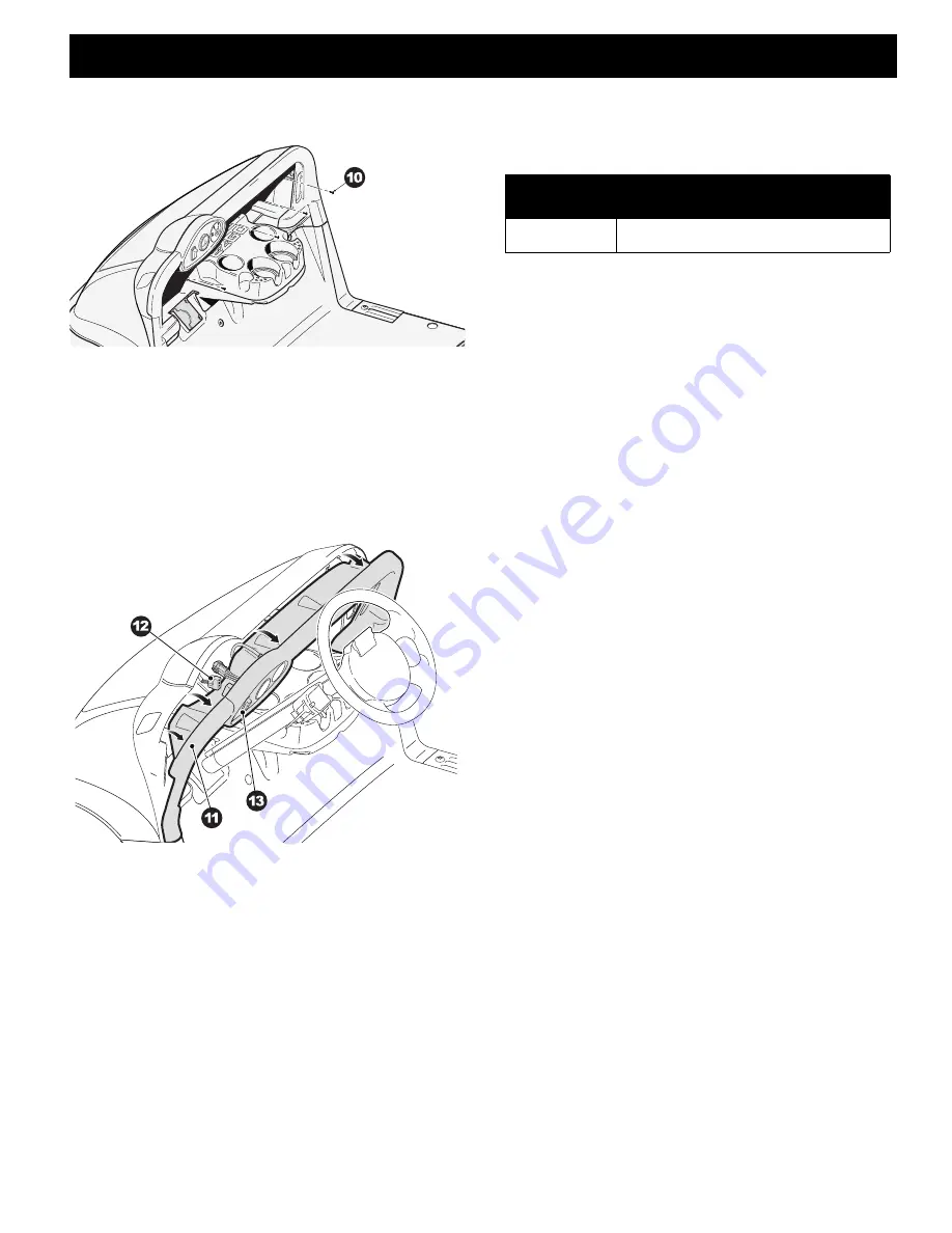
Fig. 25 Trim Panel Hardware
2. Pull the top of the trim panel (11) away from the instru-
ment panel and disconnect the accessory harness
(12) from the head light switch (13).
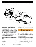
3. Depress the tabs on the top and bottom of the head-
light switch (13) and push the switch out of the trim
panel (11).
Fig. 26 Head Light Switch
4. Insert the new head light switch into the opening in the
instrument panel trim (11), making sure that the tabs
all lock in place.
5. Connect the accessory harness (12) to the headlight
switch (13).
6. Push the instrument panel trim into place making sure
that no wires are pinched.
7. Install the four Torx head screws (10) that secure the
instrument panel trim (11) to the instrument panel and
the front cowl.
Turn Signal Switch Replacement
Make sure that the vehicle key switch is in the ’OFF’
position and the key has been removed.
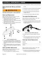
1. Remove the top part of the cup holder (ref Section B)
2. Unplug the connector from the turn signal switch har-
ness to the main electrical harness.
3. Feed the wires, connector and flasher unit down
through the bottom of the cup holder.
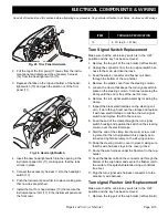
4. Remove the plastic cover from the steering column.
5. Loosen the clamp that keeps the turn signal switch in
place on the steering column. Continue loosening the
clamp until the end is free of the worm screw.
6. Remove the turn signal switch assembly including the
clamp.
7. Inspect the black electrical tape on the steering col-
umn, if worn through, remove the old tape and replace
it with new electrical tape to cushion the turn signal
switch and improve the fit to the column.
8. Feed the end of the clamp through the turn signal
switch housing and position the switch on the steering
column over the electrical tape.
9. Start the end of the clamp into the worm screw, mak-
ing sure that the turn signal switch is properly posi-
tioned and tighten securely on the steering column.
10. Snap the steering column cover in place making sure
that the wire harness stays in the cover groove.
11. Route the wire harness under the floor mat to the cup-
holder.
12. Feed the flasher unit and the connector up through the
bottom of the cup holder and secure the flasher unit to
the center of the splash shield tab using a christmas
tree rivet.
13. Plug the turn signal wire harness connector into the
accessory wire harness.
Turn signal Flasher Unit Replacement
Make sure that the vehicle key switch is in the ’OFF’
position and the key has been removed.
1. Remove the top part of the cup holder (ref Section B)
ITEM
TORQUE SPECIFICATION
10
6- 9 ft. lbs (8 - 127 Nm)


