TROUBLESHOOTING AND DIAGNOSTICS
Page O-5
Repair and Service Manual
Read all of Section B and this section before attempting any procedure. Pay particular attention to all Notes, Cautions and Warnings.
B
B
CODE
DESCRIPTION
POSSIBLE CAUSES
DIAGNOSTIC STEP
ACTION (post diagnos-
tics)
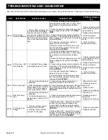
8976
AC Over Current
1. Software detects motor cur-
rent 50% higher than controller
peak rated current. NOTE: this
error is seldom seen. It is usu-
ally the result of motor parame-
ters such as stator inductance
or resistance being out of spec.
Transient Events can also
cause this error without a com-
ponent failure
1. Turn key to ’OFF’ and then back ’ON’. If
car does not run proceed to step 2.
2. Disconnect U, V, W from controller. Check
resistance between U -V, V-W, and U-W,
each should be 0.4-0.8 Ohms. If readings
are out of range see
ACTION
1
. If readings
are in range and car does not run proceed to
step 3.
3. Remove controller from the non-running
car and install it in a running car, if this vehi-
cle does not run with this controller the con-
troller is suspect. See
ACTION 2
1. Replace Motor
2. Replace Controller
9024
AC Short Circuit
1. Short circuit detected in con-
troller, motor cable or motor.
1. Turn key to ’OFF’ and then back ’ON’. If
car does not run proceed to step 2.
2. Disconnect U, V, W from controller. Check
resistance between U -V, V-W, and U-W,
each should be 0.4-0.8 Ohms. If readings
are out of range see
ACTION 1
. If readings
are in range and car does not run proceed to
step 3.
3. Remove controller from the non-running
car and install it in a running car, if this vehi-
cle does not run with this controller the con-
troller is suspect. See
ACTION 2
1. Replace Motor
2. Replace Controller
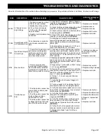
12576 DC Bus Timeout
1. DC Bus voltage has not
reached 24 volts within 10 sec-
onds after key switch start.
1. Check battery voltage across all 4 batter-
ies, voltage should read 42 VDC minimum, if
O.K. proceed to step 2.
2. Check voltage across solenoid contacts, if
more than 3 VDC but less than 24 VDC pro-
ceed to step 3, if not see
ACTION 3
.
3. Remove resistor control module connec-
tion to controller B- terminal, if error status
changes follow
ACTION 1
.
1. Replace resistor control
module.
2. If error does reoccur
then replace controller.
3. Replace solenoid.
12817 DC Bus High - Soft-
ware Detected
1. Battery Pack voltage is over
63 volts. NOTE: It is unlikely
this error will occur in the fac-
tory. If it occurs in the field dur-
ing regenerative braking,
energy is transferred from the
controller back to the battery
pack raising the DC Bus volt-
age and battery pack terminal
voltage only if the energy burn
circuit is not properly function-
ing.
1. Verify that all battery wires are securely
fastened and have less than 0.1 ohms resis-
tance between wire terminal and battery
post.
2. Check the battery voltage across all 4 bat-
teries, voltage should read 63 VDC
MAXI-
MUM
.
3. Check voltage across solenoid contacts. If
more than 3 VDC but less than 24 VDC pro-
ceed to step 3, if it does not fall in this range
follow
ACTION 3
.
4. Verify power resistor ohm reading is
between 0.2 and 0.5 ohms.
5. Remove resistor control module connec-
tion to controller B- terminal. If error status
changes follow
ACTION 1
.
1. Tighten or replace loose
or high resistance power
wire connections.
2. Replace power resistor.
3. Replace solenoid.
4. Replace resistor control
module.
5. If error continues,
replace the controller.

