Page O-10
TROUBLESHOOTING AND DIAGNOSTICS
Repair and Service Manual
Read all of Section B and this section before attempting any procedure. Pay particular attention to all Notes, Cautions and Warnings.
B
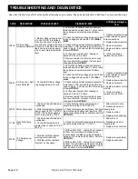
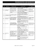
Warning Heat Sink Temp
High
1. Measured heat sink temper-
ature is greater than 85°C
(185°F) but less than 115°C
(239°F), linear torque current
reduction is active, drivability is
affected.
1. Check external heat sink temperature,
should be less than 80°C (176°F).
1. Allow time to cool.
2. Reduce payload or driv-
ing grade.
3. Replace controller.
Warning Heat Sink Temp
Sens
1. Heat sink temperature sen-
sor shorted or not connected.
1. Check external heat sink temperature, it
should be more than -20°C (-4°F) and less
than 80°C (176°F).
2. If heat sink temperature is greater than
-20°C (-4°F) and less than 70°C (158°F) then
see
ACTION 2
1. Allow time to warm or
cool depending upon tem-
perature.
2. Replace controller.
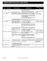
Warning Default Parameter
Default parameters are in
place.
1. This warning is normal the
first time the controller is pow-
ered up after down loading new
software.
2. If not after new software
download this indicates a prob-
lem with the EEPROM.
1. Cycle the key switch to ’OFF’ then back to
"F".
1. Replace controller.
Warning Power Reduction
1. This warning occurs in con-
junction with other motor and
heat sink temperature warn-
ings and indicates that max
torque current reduction is in
affect.
1. Refer to trouble shooting steps for the
motor and controller temperature warning
conditions.
- - -
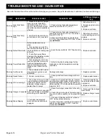
Warning Cur Meas Cal
1. The controller’s AC current
measurement system is not
calibrated
No diagnostic steps
1. Replace controller
Warning Speed Sensor
1. Sensor or wire failure
1. Check pedal functions in diagnostic real
time.
1. Replace pedal sensor.
Warning OD Current High
1. The current in an open drain
output (reverse warning alarm,
park brake, resistor control,
solenoid or brake relay) is
greater than 2.5 amps.
1. Check each output drain device (reverse
warning alarm, park brake, resistor control,
solenoid and brake relay) for a shorted con-
dition, less than 0.1 ohms with the key switch
turned to ’OFF’
1. If shorted condition is
found replace the shorted
component.
2. Replace controller.
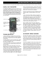
Warning Charger Connected
1. Battery charger is connected
to the car. Driving is prohibited
while charger is connected.
1. Check for charger connection to the vehi-
cle.
2. Check charger receptacle for water inges-
tion or a shorted condition (is the green LED
on?).
1. Disconnect the charger
from vehicle.
2. Replace charger recep-
tacle.
Warning Brake Slipping
1.Controller has detected
motor rotation while brake is
engaged
1. Can occur when key switch is turned to
’OFF’ while vehicle is moving.
2. Check for vehicle resistance to movement
with key switch turned to ’OFF’, if vehicle
moves see
ACTION 1
.
1. Replace motor brake
CODE
DESCRIPTION
POSSIBLE CAUSES
DIAGNOSTIC STEP
ACTION (post diagnos-
tics)

