Page O-13
TROUBLESHOOTING AND DIAGNOSTICS
Repair and Service Manual
Read all of Section B and this section before attempting any procedure. Pay particular attention to all Notes, Cautions and Warnings.
B
POWER SUPPLY
Tool List
Qty.
DVOM..........................................................................1
Check For Loose or Bare Wires
Check for loose wires at each terminal connection and
for worn insulation or bare wires touching the frame.
Bare wires may cause a short circuit.
If any DVOM readings indicate a faulty wire, it is recommended
that the condition of the terminals and wire junction be exam-
ined. A faulty wire should be replaced with one of the same
gauge and color and wired between the correct components
and wire tied to the harness bundle. The faulty wire should be
cut back close to the harness and the ends protected with vinyl
electrical tape.
Check Battery Condition
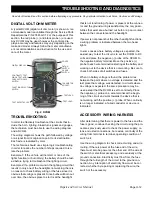
Check for adequate battery volts (nominal 12 VDC) by
setting DVOM to 30 VDC range and place the red probe
(+) on the battery post with the green wire attached.
Place the black probe (-) on the battery post with the
black wire attached. A reading of 11 VDC or greater indi-
cates adequate battery condition. No reading indicates
(a) a poor connection between the probes and the bat-
tery terminals; (b) a faulty DVOM. A voltage reading be-
low 11 volts indicates poor battery condition and the
vehicle should be recharged before proceeding with the
test.


