Page C-4
BODY
Repair and Service Manual
Read all of Section B and this section before attempting any procedure. Pay particular attention to all Notes, Cautions and Warnings.
B
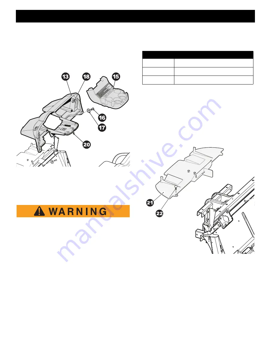
5. Remove three self threading nuts (20) securing the
cup holder assembly (15) to the instrument panel.
Remove the cup holder and disconnect the turn signal
flasher unit and the brake switch relay if the vehicle is
equipped with turn signals and brake lights.
Fig. 8 Instrument Panel and Cup Holder
6. Remove four torx screws (16) and flat washers (17)
securing the instrument panel along its lower edge
and the two torx screws (18) located near the top of
the instrument panel; one on each side. The instru-
ment panel can now be removed.
To prevent the possibility of injury or death the
correct safety label must be on the instrument
panel cup holder at all times.
Reassemble in reverse order. Replace any worn or
damaged hardware as required.
Front Splash Guard
(Ref. Fig. 9)
Tool List
Qty.
Notched Pry Bar ..........................................................1
Remove upper and lower rocker panels, cowl, instrument
panel trim and instrument panel.
1. Remove two christmas tree rivets (22) securing front
splash guard (21) to vehicle.(Ref. Fig. 2)
Reassemble in reverse order. Replace any worn or
damaged hardware as required.
Fig. 9 Front Splash Guard
20
17
18
16
13
ITEM
TORQUE SPECIFICATION
11
27 - 44 in. lbs. (3 - 5 Nm)
16
20 - 25 ft. lbs. (28 - 34 Nm)
18
13 - 16 ft. lbs. (18 - 22 Nm)


