Page E-4
ELECTRONIC SPEED CONTROL (AC MOTOR)
Repair and Service Manual
Read all of Section B and this section before attempting any procedure. Pay particular attention to all Notes, Cautions and Warnings.
B
ness to the upper terminal of the solenoid, secure in
place with a hex nut (6).
10. Reinstall the splash shield.
Replace worn or damaged hardware as required.
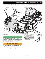
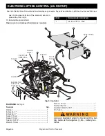
Fig. 5 Controller
Controller
(Ref Fig. 5)
Tool List
Qty.
Ratchet ........................................................................ 1
Extension, 3" ............................................................... 1
Extension, 9" ............................................................... 1
Socket, 15 mm.............................................................1
Socket, 10 mm.............................................................1
Torx Bit, T-27 IP ........................................................... 1
Wrench, 10 mm ........................................................... 1
Wrench, 15 mm............................................................1
Notched Pry Bar ..........................................................1
Insulated Wrench, 9/16"...............................................1
Pin Punch ....................................................................1
Using an insulated wrench, disconnect the bat-
tery cable at the negative (-), BL-, battery ter-
minal.
ITEM
TORQUE SPECIFICATION
7
44 - 62 in. lbs (5 - 7 Nm)
Controller
Red Wire to
Battery BL+
Red Wire from
Solenoid to
Controller B+
Heatsink
Solenoid
Resistor
Sensor
Wire to
Resistor
Resistor
Splash Shield


