ELECTRONIC SPEED CONTROL (AC MOTOR)
Page E-5
Repair and Service Manual
Read all of Section B and this section before attempting any procedure. Pay particular attention to all Notes, Cautions and Warnings.
B
B
Drain the stored energy from the controller.
Make sure that the Run/Tow switch is in the
Run position, turn the key to reverse and allow
the reverse warning indicator to run down.
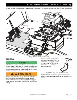
The controller is a solid state unit activated by a sole-
noid. The solenoid is hard wired to the electrical harness
and mounted to the controller heat sink. The controller is
located under the seat on the passenger side of the
vehicle. To access the controller, raise and remove the
seat bottom.
1. Disconnect the battery cable at the negative (-), BL-,
battery terminal using an insulated wrench.
2. Drain the stored energy from the controller. Place the
Run/Tow switch in the Run position, turn the key
switch to reverse, wait for the reverse warning indica-
tor to become silent, turn the key switch to the off posi-
tion and remove the key from the switch.
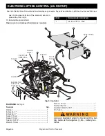
3. Remove two Torx head screws (4) securing the con-
troller splash shield to the rear body and the christmas
tree rivet (2) securing the splash shield to the control-
ler heat sink; position splash shield off to one side to
allow access to the controller.
4. Disconnect the Red positive (+) battery cable from the
upper terminal of the solenoid.
5. Disconnect the Red wire from the controller B+ termi-
nal to the lower terminal of the solenoid.
6. Remove two hex head bolts (7) securing the solenoid
to the controller heat sink, place the solenoid off to
one side out of the way.
The original solenoid is
hard wired into the electrical harness.
7. Disconnect the 2 pin connector (14) from the wire har-
ness.
8. Disconnect the 3 pin connector (12) from the resistor
control (13) connector.
9. Disconnect the 23 pin connector (9) from controller by
lifting up on the locking tab and pulling the connector
housing away from the controller.
10. Disconnect the three wires (8) from the electric motor
to terminals U, V and W by removing the three control-
ler terminal screws (11).
11. Disconnect the negative (-) battery wire (3) from the B-
terminal by removing the terminal screw (11).
12. Remove the front two hex head bolts (10) securing the
controller assembly to the floorboard and loosen the
rear hex head bolt (10). Slide the controller towards
the front of the car and lift it out.
13. To install the controller, position it on the floorboard;
making sure that all wires are not pinched or under the
controller feet; and slide it to the back aligning the slot
under the head of the hex head bolt (10). Install the
two hex head bolts (10) in the holes at the front of the
controller base. Torque all three hex head bolts as
specified in the torque table.
14. Connect the three wires from the electric motor. Blue
to the W terminal, Yellow to the V terminal and Green
to the U terminal. Install the terminal screws finger
tight, then torque as specified.
Do not over tighten
the terminal screws (11).
15. Connect the black wire (3) from the B- terminal to the
negative (-), BL-, battery terminal.
Do not over
tighten the terminal screw (11).
16. Install the solenoid on the controller heat sink using
two hex head bolts (7). Make sure that the black wires
from the solenoid to the wire harness are located at
the top of the solenoid.
17. Install the Red wire to the B+ terminal of the controller.
(Do not over tighten the terminal screw (11).
18. Plug the 23 pin connector (9); with the locking tab
located on top; from the wire harness into the socket
on the controller, push in firmly and make sure that the
locking tab is latched.
19. Check all wires to be sure they are connected to the
proper terminal.
20. Position the Splash Shield under the edge of the seat
opening, install the christmas tree rivet (2) and the two
Torx head screws (4).
21. Reconnect wires to the battery pack.
Replace any worn or damaged hardware as
required.
ITEM
TORQUE SPECIFICATION
4
18 - 27 in. lbs (2 -3 Nm)
7
44 - 62 in. lbs (5 - 7 Nm)
10
13 - 15 ft. lbs (18 - 20 Nm)
11
53 - 71 in. lbs (6 - 8Nm)


