Page F-2
FRONT SUSPENSION AND STEERING
Repair and Service Manual
Read all of Section B and this section before attempting any procedure. Pay particular attention to all Notes, Cautions and Warnings.
B
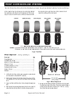
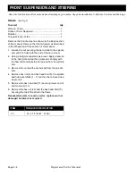
of the tread. Wear on either side of a correctly inflated
tire indicates a tire that is out of alignment. The toe-in
may be correct, but if the toe-in has not been set with
the wheels in line with the body of the vehicle it will
result in scuffing of the tire tread.
Fig. 2 Tire Wear
Wheel Alignment
(Ref Fig. 3) (Ref Fig. 4)
Tool List
Qty.
Tape Measure.............................................................. 1
Paint Marker, White ..................................................... 1
Wrench, 12 mm Open-end ..........................................1
Wrench, 17 mm ........................................................... 1
Crowfoot Wrench, 12 mm............................................ 1
Torque Wrench, ft. lbs.................................................. 1
Socket, 18 mm.............................................................1
Ratchet ........................................................................ 1
1. Lift the front of the vehicle and support on jack stands
as instructed in the SAFETY section.
2. Rotate each wheel and scribe a paint line around the
circumference of the tire at the center of the tread pat-
tern.
3. Lower vehicle with the tires in the straight ahead posi-
tion.
4. Roll vehicle forward approximately five feet in order to
allow the tires to take their normal running position
.
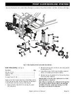
Fig. 3 Wheel Alignment
5. Measure the distance between the paint lines at both
the front and rear of the tires. The measurement taken
at the front of the tires should be 0" - 1/8" (0 - 3 mm)
less than the rear measurement
NOTES
: ILLUSTRATIONS ARE DISTORTED FOR CLARITY. DUE TO LOW WEIGHT OF
VEHICLE & LOW INFLATION PRESSURES, TIRE SHAPE WILL BE LESS PRONOUNCED.
INDICATES AREAS OF EXCESSIVE TIRE WEAR
X
+0” (0 mm)
-1/8” (3 mm)
FRONT OF VEHICLE
X

