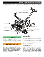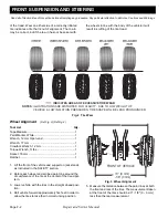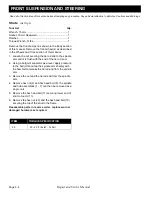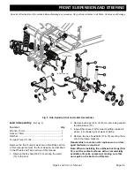
MOTOR & MOTOR BRAKE
Page G-3
Repair and Service Manual
Read all of Section B and this section before attempting any procedure. Pay particular attention to all Notes, Cautions and Warnings.
B
B
Motor Brake
The motor brake may be removed with the motor still in
the vehicle or the motor and motor brake can be removed
from the vehicle as a unit. If the motor and motor brake
are to be removed as a unit see the previous section for
instructions on the motor removal and installation.
The only service items for the motor brake are the han-
dle, the return spring and the entire motor brake assem-
bly.
Disconnect the negative (BL-) battery cable
with an insulated wrench before attempting to
disconnect wires from the motor (see safety
procedures in SAFETY section of this manual).
Tool List
Qty.
Ratchet ........................................................................ 1
Socket, 10 mm ............................................................ 1
Torx Bit, T-27 ............................................................... 1
Insulated Wrench, 9/16" .............................................. 1
Wheel Chocks ............................................................. 4
REMOVAL
1. Chock the rear wheels of the vehicle.
2. Raise and remove seat bottom.
3. Using an insulated wrench, disconnect the negative
(-) battery, BL-, cable from the battery.
4. Drain the stored energy from the controller. Place the
Run/Tow switch in the Run position, turn the key
switch to reverse, wait for the reverse warning indica-
tor to become silent turn the key switch to the off posi-
tion and remove the key from the switch.
5. Remove the two Torx head screws and the rear
access cover from the bagwell area.
6. Disconnect wire harness from motor brake.
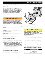
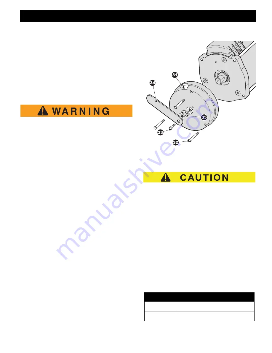
7. Remove three hex head bolts (32) from the motor
brake assembly (31).
Fig. 6 Motor Brake
8. Removing the hex head bolt (33) will allow the handle
(34) and the return spring (35) to be removed.
DO NOT over rotate the brake release handle. Over rotat-
ing the handle will damage the brake assembly.
DO NOT drop the brake assembly. Dropping or hitting the
brake assembly will damage it.
INSTALLATION
1. Position the brake with the connector at the top as
shown above and install the three hex head bolts (32)
loosely.
2. Connect the wire harness to the motor brake and
move the Run/Tow switch to the ’TOW’ position. This
will provide power to the brake to align the disc mate-
rial.
3. Tighten the three hex head bolts evenly to the speci-
fied torque.
4. Move the Run/Tow switch to the ’RUN’ position.
Replace worn or damaged hardware as required.
ITEM
TORQUE SPECIFICATION
32
53 - 71 in. lbs (6 - 8 Nm)
33
18 - 27 in. lbs (2 - 3 Nm)

