background image

BRAKES

Page D-12

Repair and Service Manual

Read all of Section B and this section before attempting any procedure. Pay particular attention to all Notes, Cautions and Warnings

Fig. 9  Parking Brake System Components

Boot (If equipped)

Parking Brake
Cable

Part of
Frame

Equalizer

Park

Brake

Lever

Jam Nut

Clevis
Yoke

Pulley

Support
Bracket

Park Brake

Lever Cable

Retaining

Ring

Center
Console

Subframe

Parking
Brake
Cable

Parking
Brake
Lever

Summary of Contents for WorkHorse ST 480

Page 1: ...R ST ST 480 GASOLINE POWERED UTILITY VEHICLE ISSUED 2001 REVISED APRIL 2011 TECHNICIAN S REPAIR AND SERVICE MANUAL 28580 G01 ...

Page 2: ......

Page 3: ......

Page 4: ......

Page 5: ......

Page 6: ......

Page 7: ......

Page 8: ......

Page 9: ......

Page 10: ......

Page 11: ......

Page 12: ......

Page 13: ......

Page 14: ......

Page 15: ......

Page 16: ......

Page 17: ......

Page 18: ......

Page 19: ......

Page 20: ......

Page 21: ......

Page 22: ......

Page 23: ......

Page 24: ......

Page 25: ......

Page 26: ......

Page 27: ......

Page 28: ......

Page 29: ......

Page 30: ......

Page 31: ......

Page 32: ......

Page 33: ......

Page 34: ......

Page 35: ......

Page 36: ......

Page 37: ......

Page 38: ......

Page 39: ......

Page 40: ......

Page 41: ......

Page 42: ......

Page 43: ......

Page 44: ......

Page 45: ... to all Notes Fig 1 Hydraulic Brake System Components Shaft Bellcrank Brake Pedal Part of Frame Master Cylinder Brake Light Switch Plug Banjo Bolt Copper Gasket Secondary Brake Line Primary Brake Line Bushing Bushing Clip Flexible Brake Hose Linkage Rod Part of Frame Torsion Spring Self Adjusting Wheel Brake Mechanical Parking Brake Lever ...

Page 46: ...es a parking feature consisting of a lever and strut The lever is applied by a cable attached to the parking brake lever hand operated The parking brake is used to retain the vehicle when stationary It may also be used as an emergency brake in the event of hydraulic system failure MAINTENANCE Daily Brake Performance Test To assure correct braking performance all peri odic maintenance inspections a...

Page 47: ...ver seat To prevent contamination when checking fluid wipe off any dirt from fill cap before removing it Reservoir fluid level should be checked per PERIODIC SERVICE SCHEDULE in Section A When required clean brake fluid should be added to maintain fluid level 1 4 6 mm from top of reservoir Use fresh DOT 3 stan dard automotive brake fluid Master Cylinder Replacement Tool List Qty Required Insulated...

Page 48: ... washer into master cylinder make sure rod is through washer inside boot Snap rubber boot back onto master cylinder Install both clevis yokes back onto bellcrank using clevis pins and new cotter pins To prevent brake failure resulting from contaminated brake fluid never reuse any excess fluid or return to the original container Dispose of brake fluid properly Fill reservoir with DOT 3 brake fluid ...

Page 49: ...hammer to loosen it from the axle shaft or use drum puller P N 15947 G1 If shoes interfere with drum removal rotate adjuster bolt on back side of backing plate towards the axle to retract shoes and remove brake drum Pay particular attention to the location of the inner brake drum washer inside the brake drum which may be on the axle shaft or attached to the rear of the drum hub This washer must be...

Page 50: ...ig 5 Wheel Brake Components Lock Nut Brake Shoe Cotter Pin Inner Brake Drum Washer Cup and Spring Lower Shoe to Shoe Spring Upper Shoe to Shoe Spring Allen Head Bolt Dust Cover Wheel Cylinder Adjuster Drum Belleville Washer Parking Brake Strut and Lever Wheel Cylinder Bolt Adjuster Bolt Castellated Nut Outer Brake Drum Washer Spindle Cap Banjo Bolt Copper Gaskets Brake Line ...

Page 51: ...heel cylinder must be removed begin by loosen ing and removing the brake line from the back of the wheel cylinder Next remove the wheel cylinder bolts and remove the wheel cylinder from the backing plate Cleaning And Inspection The drum must not be turned to true a worn friction surface Turn ing will make the drum too thin causing drum and brake failure which could cause severe injury or death Ins...

Page 52: ...m torque Reconnect and tighten the brake fluid line to 124 177 in lbs 14 20 Nm torque Position shoes on backing plate and install hold down springs Install parking brake strut with tab on strut engaged in brake shoe web Place upper end of shoe webs against wheel cylinder and install upper shoe to shoe spring Remove wheel cylinder clamp Install lower shoe to shoe spring Install wheel and drum See B...

Page 53: ...banjo bolt to 124 177 in lbs 14 20 Nm torque Tighten allen head bolts and lock nuts to 23 27 ft lbs 31 37 Nm torque BLEEDING AND FLUSHING Tool List Qty Required Shop towels A R Hose A R Clean container 1 Brake fluid DOT 3 A R Wrench 1 4 box end 1 Crowfoot wrench 1 4 3 8 drive 1 Torque wrench 3 8 drive in lbs 1 Bleeding The brake hydraulic system must be free of air to func tion properly Any air in...

Page 54: ...he bleeder screw and release the brake pedal slowly Then repeat Steps 2 and 3 The bleeder valve at the wheel cylinder must be closed at the end of each stroke and before the brake pedal is released to insure that air cannot enter the system It is also important that the brake pedal be returned to full up position 4 When fluid coming from the submerged end of the hose is clear and free of bubbles c...

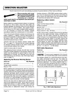
Page 55: ... periodic lubrication with a dry graphite or molybdenum disulfide lubricant Raise the lever and spray into the underside to access the pivot arm and ratchet mechanism of the park ing brake See Section A Periodic Service Schedule for recommended lubrication schedule Adjustment The parking brake adjustment is made at the clevis yoke on the end of the parking brake lever cable located under the front...

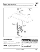
Page 56: ...y particular attention to all Notes Cautions and Warnings Fig 9 Parking Brake System Components Boot If equipped Parking Brake Cable Part of Frame Equalizer Park Brake Lever Jam Nut Clevis Yoke Pulley Support Bracket Park Brake Lever Cable Retaining Ring Center Console Subframe Parking Brake Cable Parking Brake Lever ...

Page 57: ......

Page 58: ......

Page 59: ......

Page 60: ......

Page 61: ......

Page 62: ......

Page 63: ......

Page 64: ......

Page 65: ......

Page 66: ......

Page 67: ......

Page 68: ......

Page 69: ......

Page 70: ......

Page 71: ......

Page 72: ......

Page 73: ......

Page 74: ......

Page 75: ......

Page 76: ......

Page 77: ......

Page 78: ......

Page 79: ......

Page 80: ......

Page 81: ......

Page 82: ......

Page 83: ......

Page 84: ......

Page 85: ......

Page 86: ......

Page 87: ......

Page 88: ......

Page 89: ......

Page 90: ......

Page 91: ......

Page 92: ......

Page 93: ......

Page 94: ......

Page 95: ......

Page 96: ......

Page 97: ......

Page 98: ......

Page 99: ......

Page 100: ......

Page 101: ......

Page 102: ......

Page 103: ......

Page 104: ......

Page 105: ......

Page 106: ......

Page 107: ......

Page 108: ......

Page 109: ......

Page 110: ......

Page 111: ......

Page 112: ......

Page 113: ......

Page 114: ......

Page 115: ......

Page 116: ......

Page 117: ......

Page 118: ......

Page 119: ......

Page 120: ......

Page 121: ......

Page 122: ......

Page 123: ......

Page 124: ......

Page 125: ......

Page 126: ......

Page 127: ......

Page 128: ......

Page 129: ......

Page 130: ......

Page 131: ......

Page 132: ......

Page 133: ......

Page 134: ......

Page 135: ......

Page 136: ......

Page 137: ......

Page 138: ......

Page 139: ......

Page 140: ......

Page 141: ......

Page 142: ......

Page 143: ......

Page 144: ......

Page 145: ......

Page 146: ......

Page 147: ......

Page 148: ......

Page 149: ......

Page 150: ......

Page 151: ......

Page 152: ......

Page 153: ......

Page 154: ......

Page 155: ......

Page 156: ......

Page 157: ......

Page 158: ......

Page 159: ......

Page 160: ......

Page 161: ......

Page 162: ......

Page 163: ......

Page 164: ......

Reviews: