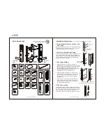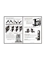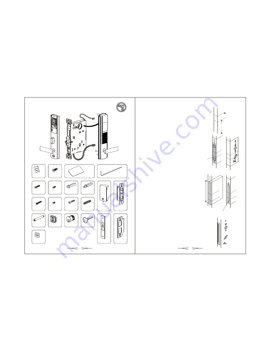
1. Draw horizontal lines on the door and
door edge
Measure for the lever center line on the door and door edge
36" (914mm) above the floor and then draw out the latch
center line according to the paper template.
2.
Set the central point for drilling
Following the paper template, determine whether the door is
right- or left-handed and then place the appropriate paper
template to the door and door edge, aligning with the latch
center line and the lever center line (as illustrated) and
marking the centers of the holes.
3.
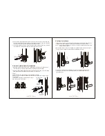
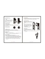
Door Edge Drilling
1
.
Following the marks, drill 2 holes, 1" (25.4mm) in
diameter and 4-17/32" (115mm) deep on the door edge
and then, based on the positions of the 2 holes, chisel
out a rectangular groove (the line segments on the
paper template) 1" (25.4mm) in width, 6-3/8" (162mm)
in height and 4-17/32" (115mm) deep for the
installation of the lock case (Illustration 1).
2
.
Following the paper template, cut a groove 1-5/16"
(33mm) in width, 8-1/32" (204mm) in height and 1/4"
(6.5mm) deep on the door edge to provide a level
door edge surface once the faceplate is installed
(Illustration 2).
3
.
Finally, following the marks on the paper template,
drill two guiding holes (screw holes) 1/8" (3mm) in
diameter and 19/32" (15mm) deep to complete the
door edge drilling (Illustration 2)
。
Installation Procedures
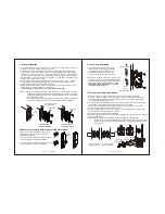
4. Door face drilling
Following the markings of the paper template and the size
requirements, drill the holes for the lock cylinder, the thumb
turn, and the lever and six other penetrating holes. Please
be sure to drill from the inside out and the outside in
respectively to prevent burrs and other damage to the door.
(In all illustrations a right-hand door is the example)
x
1
x
6
x
2
x
2
x
1
x
2
x
1
x
1
x
1
x
1
x
2
x
1
x
1
x
2
x
6
Metal screw
Proximity card
Hex wrench
Screw for
screw post
Exterior
spindle
Interior
spindle
Strike screw
x
2
Rotating
plate screw
13mm
Interior lock
body screw
Spring
Battery cover
Strike box
Screw Post
Cylinder
Key
x
1
Fixing plate
x
2
Faceplate
screw
x
2
Rotating Plate
x
1
Nameplate
Faceplate
Strike
1
2
封面裡
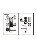
Parts Introduction
Do not use an electric screwdriver
when installing the product !
Interior lock
body
Exterior lock
body
Mortise
lock case
Center line of
the door edge
6
-3
/8
"(
1
6
2
m
m
)
ø1/8" (ø3mm) guiding hole of depth 19/32" (15mm)
(
)
Illustration 1
Latch center
line
Lever center line
36" (914mm)
(
)
Illustration 2


