5
6
6
.
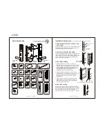
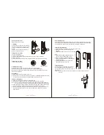
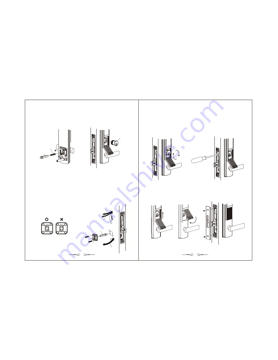
First pull the IC wire through the upper wire exit hole to the room side and then insert the
exterior spindle of the exterior lock body into the square hole that corresponds to the latch
to mount it to the door, with the screw posts penetrating the latch.
7
.
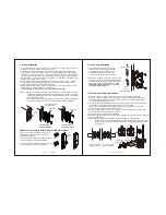
Lift the lock cylinder cover from its bottom before pulling straight down and then rotate the
lock cylinder into the latch to temporarily position the exterior lock body.
Cylinder
Spring
Exterior spindle
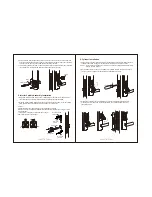
8. Interior Spindle Assembly Installation
1. Adjust the direction of the arrow on the rotating plate so that it points to the end of the
lever and then insert the interior spindle into the rotating plate as illustrated.
2. With the interior spindle inserted into the square hole of the lock case, press the rotating
plate against the door and fasten it with 2 screws for screw posts.
Caution :
Please rotate the lever downward to check if it functions normally.
If the lever cannot be rotated downward, this indicates that the direction changer is in the
wrong direction.
To correct this, simply take off the direction changer
and rotate it before re-inserting it.
Wire for the outside
Lock body
Wire for the
lock case
Interior spindle
Wire for the
lock case
Rotating plate
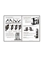
9. Cylinder Installation
1
.
Fasten the lock cylinder clockwise into the threaded latch so that the surface of the lock
cylinder is flush with the edge, with the keyhole located at the 6 o'clock position.
Caution :
, do not insert a flat head screwdriver while
rotating the lock cylinder.
2
.
On the side of the lock case, use a screwdriver to fasten the lock case. Use the key to
turn the cylinder to make sure that the latch bolt operates smoothly.
To prevent the damage of the cylinder
3
.
Closing the cylinder cover: as illustrated, push the cover upward to the top before
pressing it in
, which is fastened with 2 front
faceplate screws.
from the bottom install the faceplate


